Turnbuckle release mechanism

  • Thread starter Robbwal199
  • Start date
  • #1
Robbwal199
22
4
TL;DR Summary
Looking for a way to manipulate one end fitting of a turnbuckle to hold tension but be able to release all tension on demand.
I'm looking to build an adjustable mechanism for a concussion model rig. The premise is that it must be able to tilt the skull, and release the tilt at the moment of impact to not affect how the head whiplashes.

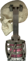
As you can see in Picture 1, I originally designed two platforms to fit onto the model, connected to one another by a mini ratchet strap.

The idea as shown in Picture 2, is that the model could pre-set to an angle, where it accelerates down a track using a pneumatic actuator and the force of the sudden stop at the end of the track would blow the bottom hooks off their anchor point. This would release all the tension in the straps, meaning the skull could whiplash freely mimicking a concussion.

However, I was suggested to use mini turnbuckles (open end full length ~ 250 mm, can be any end fittings) as opposed to ratchet straps, and to also change the mechanism of releasing the bottom attachment due to likely low reliability of release.

So this leaves me with a question: What is the best way of manipulating the bottom fitting of a turnbuckle to tilt the skull, but release at impact?

Any suggestions would be much appreciated. 1701357260572.png1701357426935.png1701357464170.png
 
Engineering news on Phys.org
  • #2
Robbwal199 said:
So this leaves me with a question: What is the best way of manipulating the bottom fitting of a turnbuckle to tilt the skull, but release at impact?
I would consider an over-centre latch, loaded with a mass, or with a trigger, so it will release on impact.
Such latches are made to hold the tail-gates of trailers, and the sides of small trucks. They are also used for work holding during machining operations. In order to get a quick, clean release, you will need to adjust them to the edge of stability.

You might design your own OC latch for the specific application. It can be as simple as two hooked or stepped plates, with a separate small plate that locks them until triggered.
 
  • Like
Likes Lnewqban and Robbwal199
  • #3
Welcome to PF. :smile:

What is the purpose of tilting the head forward against the spring force of the neckpiece? Is it just to hold the head position steady during the hard acceleration to impact speed down the track? Are you trying to model this as if the person were actively holding their head forward with their neck muscles during hard acceleration (like launching a dragster)? Or should the head be in a natural position at the moment of impact to simulate a crash at a constant high speed?

Unless you are wanting to simulate the case of the crash happening during very high acceleration, I'd leave the head up in the natural human position and hold it steady there (probably with solenoids) during the acceleration phase and release it once terminal velocity is acheived. How much time is available between reaching terminal velocity and the crash? Solenoids can release pretty quickly...
 
  • Like
Likes Lnewqban
  • #4
berkeman said:
Welcome to PF. :smile:

What is the purpose of tilting the head forward against the spring force of the neckpiece? Is it just to hold the head position steady during the hard acceleration to impact speed down the track? Are you trying to model this as if the person were actively holding their head forward with their neck muscles during hard acceleration (like launching a dragster)? Or should the head be in a natural position at the moment of impact to simulate a crash at a constant high speed?

Unless you are wanting to simulate the case of the crash happening during very high acceleration, I'd leave the head up in the natural human position and hold it steady there (probably with solenoids) during the acceleration phase and release it once terminal velocity is acheived. How much time is available between reaching terminal velocity and the crash? Solenoids can release pretty quickly...
Thanks for your reply Berkeman.

The purpose of the tilting is to investigate the differences in the rotational acceleration experienced by the skull due to differences in head angle at the moment of impact. So if the head was in flexion i.e. looking down at the toes at the moment a person is tackled chest-high, is this less likely to incur a concussion than someone looking up to the sky? The release mechanism would favourably have the head still set at its preset angle at the moment of impact rather than neutral.
 
  • #5
Robbwal199 said:
The purpose of the tilting is to investigate the differences in the rotational acceleration experienced by the skull due to differences in head angle at the moment of impact.
Welcome, @Robbwal199 !

I see a problem with the mass and freedom to move after impact of those turnbuckles.

Also, the pink elastic cylinder is going to turn some kinetic energy into elastic potential energy, situation that does not exist in the natural neck.

From personal experience with motorcycle crashes, the muscles of the neck are meaningless when trying to restrain a head and a helmet during even a moderate impact.

For ideas, look up “Quick release inertial mechanism”.
 
  • #6
Lnewqban said:
Welcome, @Robbwal199 !

I see a problem with the mass and freedom to move after impact of those turnbuckles.

Also, the pink elastic cylinder is going to turn some kinetic energy into elastic potential energy, situation that does not exist in the natural neck.

From personal experience with motorcycle crashes, the muscles of the neck are meaningless when trying to restrain a head and a helmet during even a moderate impact.
Thanks Lnewqban,

There is certainly some issues with the neck design, but unfortunately the model is already created so my focus is solely on implementing this tilt mechanism. The resistance for the first maybe 15 degrees of tilting is low, but gets increasingly more difficult after this.

Re mass and freedom to move of the turnbuckles, what do you exactly mean by this? Is it that the mass of the released turnbuckle would significantly affect head movement?
 

Attachments

  • Isolated skull.png
    Isolated skull.png
    57.9 KB · Views: 28
  • #7
Robbwal199 said:
...
Re mass and freedom to move of the turnbuckles, what do you exactly mean by this? Is it that the mass of the released turnbuckle would significantly affect head movement?
Yes.
Those may even damage the skull when loose right after impact, I believe.
I would move the releasing mechanism to the top end, or even aft, in such a way that it is not connected to the tilting model during impact in any way.
 
  • Like
Likes berkeman and Robbwal199
  • #8
How about a sacrificial release?

Use some sewing thread (or maybe yarn) to attached the turnbuckles to the fixture.

Some experimenting required to calibrate.

Cheers,
Tom
 
  • #9
Tom.G said:
How about a sacrificial release?

Use some sewing thread (or maybe yarn) to attached the turnbuckles to the fixture.

Some experimenting required to calibrate.

Cheers,
Tom
Thanks Tom, certainly something I considered but two issues: 1. finding string which can hold the huge amount of tension in turnbuckle and also snap on impact 2. model will be run dozens of times for testing so time for replacing string would not be ideal
 
  • #10
Robbwal199 said:
The purpose of the tilting is to investigate the differences in the rotational acceleration experienced by the skull due to differences in head angle at the moment of impact. So if the head was in flexion i.e. looking down at the toes at the moment a person is tackled chest-high, is this less likely to incur a concussion than someone looking up to the sky?
Robbwal199 said:
but unfortunately the model is already created so my focus is solely on implementing this tilt mechanism.
I have a problem with this overall setup and the PI (primary investigator) goal that you have stated so far.

As a medic, I know that holding your head forward in a non-accelerating frame is not going to involve your anterior flexor muscles in your neck. Just try it -- once you bend your neck and head forward, it takes zero effort from your anterior neck flexor muscles. Your head just rests there. So designing an experiment to test for concussions when the head is passively in that position should absolutely not involve any pre-tension forces during the impact.

Can you please check with your PI and look at their grant text to be sure that you are doing what will provide valuable data? Thanks.

1701470630295.png

https://time.com/3595976/spine-phone/
 
  • Like
Likes Lnewqban
  • #11
I think the OP is treating the 'head forward' position as the head being positioned for reading. The elastic mount is then considered as the posterior, counter balancing, muscle.

The problem I see with this is that once the head has traveled to its normal upright position (facing straight ahead), the elastic mount will resist the rearward force, while in a human the posterior muscles are still being commanded to contract.

If the above happens to be correct, the OPs approach will under-estimate both the travel and G force of the head.

A possible enhancement/correction could be have the head mounted on a pivot and an elastic band behind it pulling down at an angle to simulate the posterior muscle.

That still leaves the original release problem to be solved though.

An almost-after-thought: Weight the head so its CG is anatomically correct relative to the pivot point. Then suspend the whole assembly as a pendulum, and release it so the fixture hits an immovable object (brick wall?).

Cheers,
Tom
 
  • #12
berkeman said:
I have a problem with this overall setup and the PI (primary investigator) goal that you have stated so far.

As a medic, I know that holding your head forward in a non-accelerating frame is not going to involve your anterior flexor muscles in your neck. Just try it -- once you bend your neck and head forward, it takes zero effort from your anterior neck flexor muscles. Your head just rests there. So designing an experiment to test for concussions when the head is passively in that position should absolutely not involve any pre-tension forces during the impact.

Can you please check with your PI and look at their grant text to be sure that you are doing what will provide valuable data? Thanks.

View attachment 336460
https://time.com/3595976/spine-phone/
Thanks Berkeman and fully agree with your observation. The current design almost has the head and neck combined into one system/body.

The issue is that this model was made years ago and is a continuation project by a new person each year, meaning I only joined in the last few months. As such, ripping apart the whole rig to try and separate the head and neck per say is not feasible. But yes, absolutely a limitation of the whole project. The project is more small-scaled, where the results obtained are not going to be released to academia etc. so an acceptance of error is present.
 
  • Informative
Likes berkeman
  • #13
Tom.G said:
1. The problem I see with this is that once the head has travelled to its normal upright position (facing straight ahead), the elastic mount will resist the rearward force, while in a human the posterior muscles are still being commanded to contract. 2. An almost-after-thought: Weight the head so its CG is anatomically correct relative to the pivot point. Then suspend the whole assembly as a pendulum, and release it so the fixture hits an immovable object (brick wall?).

1. something similar to what you are proposing has already been observed in running the model without any tilt. The momentum of the initial jolt into flexion seems to pause about 3/4 of the way into peak flexion, and then resume into the peak flexion position. Its likely to do with the springs on neck, some seem to get locked up with the sudden transition, temporarily halting flexion, finally unlocking themselves and allowing the model to continue.

2. The skull is already weighted to the same as a human head, finding CG relative to pivot point may be difficult. Unsure in grasping this pendulum idea; are the fixtures you're referencing the tilting platforms or the skull? Regardless, given the quite violent nature of running this model at 5 bar of pressure, anything impacting something solid would cause momentous damage.
 
  • #14
Robbwal199 said:
are the fixtures you're referencing the tilting platforms or the skull?
I was thinking of the platform, that which everything is mounted on, the lower end of both the turnbuckles and the neck.
If that is too damaging to the hardware, perhaps you could mount the whole thing on a larger-dimensioned solid block (or sheet) of wood. That way the wood block could take the surface damage of hitting a brick wall.

Re-reading your early posts, pointed out another concerning point. Any inertial latch release will by definition release only after the deceleration starts!

A release mechanism wiil have to be mechanically triggered by contacting the stop at the moment the platform contacts it.

Cheers,
Tom

(p.s. Isn't Engineering FUN?)
 
  • #15
Robbwal199 said:
Thanks Berkeman and fully agree with your observation. The current design almost has the head and neck combined into one system/body.

... As such, ripping apart the whole rig to try and separate the head and neck per say is not feasible.
Would an adjustable modification of the angle that the base of the rubber neck makes with the sliding track solve that problem?

Being able to tilt the skull and the neck together would remove any pre-tension-compression at the moment of impact, not affecting how the head whiplashes, regardless the chosen tilt angle.
 
  • #16
Tom.G said:
I was thinking of the platform, that which everything is mounted on, the lower end of both the turnbuckles and the neck.
If that is too damaging to the hardware, perhaps you could mount the whole thing on a larger-dimensioned solid block (or sheet) of wood. That way the wood block could take the surface damage of hitting a brick wall.

Re-reading your early posts, pointed out another concerning point. Any inertial latch release will by definition release only after the deceleration starts!

A release mechanism wiil have to be mechanically triggered by contacting the stop at the moment the platform contacts it.

Cheers,
Tom

(p.s. Isn't Engineering FUN?)
I believe there would be far too many issues in attaching a block to the track for what its worth, also, the mass it would add.

The inertial latch release idea isn't perfect as you pointed out. A pneumatic piston placed at the end of track, which when activated, moves into the the eye of the turnbuckle, pushing whatever locking mechanism is there out of place could be more favourable. Finding a method of activating it at the perfect moment using some sort of magnetic sensor or something could be difficult. What are your thoughts on this suggestion?
 
Last edited:
  • #17
Very good suggestion and possibly something I didn't consider since the attachment point to the track was done before I joined the project. As I said to Tom, I'm very unsure on how much flexibility there is with the current attachment mechanism but something I will have to look into. I think it is likely I would find the same issue with releasing the tilt here also however.
 
  • #18
Have a look at the trigger mechanism of eg cross-bow or 'rubber bands' spear-gun ??
 
  • Like
Likes Robbwal199
  • #19
Robbwal199 said:
Very good suggestion and possibly something I didn't consider since the attachment point to the track was done before I joined the project. As I said to Tom, I'm very unsure on how much flexibility there is with the current attachment mechanism but something I will have to look into. I think it is likely I would find the same issue with releasing the tilt here also however.
If the bottom of the neck is too difficult to modify, you could try the connection of the bracket holding the skull to the top of the neck.
After a pre-tilt is achieved, no triggering mechanism would be needed, just like in real life.
There would not be any tension for your turnbuckles to hold.
 
  • Like
Likes Robbwal199
  • #20
Unfamiliar with how crossbow triggers work but intuitively, a trigger would need to be pressed somewhere on the model body in order to release tension yes? @Nik_2213
 
  • #21
Lnewqban said:
If the bottom of the neck is too difficult to modify, you could try the connection of the bracket holding the skull to the top of the neck.
After a pre-tilt is achieved, no triggering mechanism would be needed, just like in real life.
There would not be any tension for your turnbuckles to hold.
I dont believe this would be possible as the head/neck are almost one system by their connection with a bundle of steel rods shown in picture previously. Even if I was able to pre-set tilt with a ramp at top of neck, this would affect the heads movement in the opposite direction?
 
  • #22
Robbwal199 said:
Finding a method of activating it at the perfect moment using some sort of magnetic sensor or something could be difficult. What are your thoughts on this suggestion?

Unfortunately, quite impractical to implement accurately.

How about release lever(s) (posts) on your fixture that are horizontal and stick out a little from the leading edge of the fixture. They could contact the barrier that stops the travel just before the fixture hits the stop. Timing could be varied by adjusting their length (how far they stick out from the fixture).

Cheers,
Tom
 
  • #23
Tom.G said:
Unfortunately, quite impractical to implement accurately.

How about release lever(s) (posts) on your fixture that are horizontal and stick out a little from the leading edge of the fixture. They could contact the barrier that stops the travel just before the fixture hits the stop. Timing could be varied by adjusting their length (how far they stick out from the fixture).

Cheers,
Tom
Hi Tom,

My apologies for not providing more detail about the track/stopping mechanism (see picture attached). The hardstop is initiated by the "stroke length" of the actuator being reached. Your suggestion did make me think about placing something past the hardstop (just left of end of track in picture) that could remove eg: a latch holding the eye of a turnbuckle in place.
Model skull in rig.PNG
 
Last edited by a moderator:
  • Like
Likes Tom.G

What is a turnbuckle release mechanism?

A turnbuckle release mechanism is a device that allows for the quick and easy release of tension in a turnbuckle. A turnbuckle is a mechanical fastener used to adjust the tension or length of ropes, cables, tie rods, and other tensioning systems. The release mechanism typically involves a trigger or lever that, when activated, releases the locking mechanism holding the turnbuckle in tension.

How does a turnbuckle release mechanism work?

The turnbuckle release mechanism works by incorporating a quick-release feature into the standard turnbuckle design. This usually involves a spring-loaded pin or a similar device that locks the turnbuckle's adjusting screw in place. When the release mechanism's trigger or lever is activated, the pin is retracted, allowing the turnbuckle to be freely adjusted or completely detached without the need for rotating the body or the end fittings.

What are the common applications of a turnbuckle release mechanism?

Turnbuckle release mechanisms are commonly used in applications where rapid changes in tension are required or where frequent adjustments are necessary. This includes theatrical rigging, where scenery and lights must be moved quickly and safely, in shipping to secure heavy loads, and in sports equipment where safety and maintenance require quick adjustments, such as in wrestling or boxing rings.

What materials are used to make turnbuckle release mechanisms?

Turnbuckle release mechanisms are typically made from materials that provide strength and durability, such as stainless steel, carbon steel, or aluminum. The choice of material depends on the required strength, environmental conditions, and whether corrosion resistance is necessary. Stainless steel is particularly popular for marine applications due to its resistance to rust and corrosion.

What should be considered when selecting a turnbuckle release mechanism?

When selecting a turnbuckle release mechanism, consider the load requirements, the environment in which it will be used, the frequency of adjustments, and ease of use. It's important to choose a mechanism that can handle the maximum expected load without failure. Environmental factors such as exposure to chemicals, saltwater, or extreme temperatures should also influence the choice of material and design to ensure longevity and reliable performance. Additionally, the mechanism should allow for easy and safe operation to prevent accidents or injuries during adjustments.

Similar threads

Replies
4
Views
4K
  • Electrical Engineering
2
Replies
59
Views
6K
  • Introductory Physics Homework Help
Replies
5
Views
2K
Replies
2
Views
5K
  • Sticky
  • Aerospace Engineering
2
Replies
48
Views
60K
Replies
9
Views
2K
Replies
2
Views
7K
Back
Top