Understanding dependent sources in electric circuits

  • #1
zenterix
480
70
TL;DR Summary
In the shown depictions of a dependent source there is an input side and an output side. How exactly are they connected?
The amount of voltage provided by an independent voltage source and the amount of current provided by an independent current source do not depend on the circuit they are in.

There are other types of sources, however, that do depend on the circuit they are in. That is, such dependent sources depend on (ie, are controlled by) other parameters in the circuit.

Here are depictions of four types of dependent sources

1697170393475.png


To summarize my question: how is the left side connected to the right side in practice?

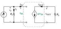
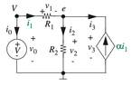
For example, consider the following circuit containing a current controlled current source (case b above)
1697174554310.png


How exactly is it that the depicted input port affects the dependent current source?

I see that there is a connection in the center bottom. Is the connection between the input side and output side as simple as this or is the depiction somehow simplified?

It seems there must be some other connection. As far as I can tell, basic circuit analysis would predict no current in the bottom connection part.
 

Attachments

  • 1697174115703.png
    1697174115703.png
    5.9 KB · Views: 33
Engineering news on Phys.org
  • #2
These are idealized circuit models. There is no "why, or how", it is defined to be that way; by magic, I suppose. You can not build this circuit element in the real world, but they can be useful things to build simple models of real world processes... sometimes.
 
  • Like
Likes DeBangis21 and alan123hk
  • #3
The question cannot be answered in general, because the "connection" between input and output is physically different for each active element working as a "dependent source".
But if you know the working principle of the electron tube or the transistors (FET or BJT), then the answer is automatically given.
 
  • #4
zenterix said:
It seems there must be some other connection. As far as I can tell, basic circuit analysis would predict no current in the bottom connection part
The basic input-output relationship of the two-port network is defined by the equation. Whether there is a bottom connection depends on your application and decision. If connected together the potential is the same, if not connected the potential difference is undefined
For example, there is no connection between the input and output of an isolation transformer through which actual current can pass.
 
  • #5
LvW said:
The question cannot be answered in general, because the "connection" between input and output is physically different for each active element working as a "dependent source".
But if you know the working principle of the electron tube or the transistors (FET or BJT), then the answer is automatically given.

How about if we limit the scope to a specific example?

Below is an example of a circuit containing a CCCS. I still can't really see/understand the mechanism by which the dependent current source depends on a specific current ##i_1## below.

Consider the following reasoning that appears in the book I am reading.

We have the following general depiction of a circuit containing a dependent current source

1697185411123.png


Now suppose that the circuit on the left has the node voltages as shown below

1697185462026.png


Then we can express the element law for the dependent source as a function of the node voltages:

$$I=f(i)=f\left (\frac{e_a-e_b}{R}\right )$$

And then the book gives a concrete example:

1697186025696.png


This circuit has one dependent source, namely a CCCS (current controlled current source).

To analyze this circuit using the node method, we first replace its CCCS with an independent current source carrying a known current, say ##I##, and analyze the resulting circuit.
The circuit becomes

1697186001978.png


We can easily solve the above circuit with the node method, and the solution for ##i_1## is

$$i_1=-\frac{R_2}{R_1+R_2}I+\frac{1}{R_1+R_2}V$$

Of particular interest is the value of ##i_1## because ##i_1## controls the CCCS. Using the result for ##i_1## we next write

$$I=\alpha i_1=\left ( -\frac{R_2}{R_1+R_2}I+\frac{1}{R_1+R_2}V \right )\tag{3.49}$$

and we solve for ##I##

$$I=\frac{\alpha}{R_1+(1+\alpha)R_2}V\tag{3.50}$$

The actual value of the CCCS is now known

Finally we back-substitute Equation 3.50, namely the actual value of ##I##, into the equations that formed the solution of the circuit in Figure 3.10, thus completing the analysis of the circuit in Figure 3.26.

We get all the solutions in terms of just ##V## and no longer ##I##.

For example,

$$i_1=\frac{1}{R_1+(1+\alpha)R_2}V$$
 

Attachments

  • 1697185589557.png
    1697185589557.png
    4 KB · Views: 31
  • #7
It has been accurately pointed out that dependent sources are 'ideal' devices. It is worth noting that completely 'independent' devices are also 'ideal.' Coping with the difference between ideal and actual is one definition of Engineering.
 
  • #8
berkeman said:
Perhaps look into how Current Mirrors work
Should this be a current-controlled current source, a current-controlled voltage, a voltage-controlled current source or a voltage-controlled voltage source?
If it is CCCS, it corresponds IOUT /I REF
If it is CCVS, it corresponds VOUT / IREF
If it is VCCS it corresponds IOUT /V CC
If it is VCVS, it corresponds VOUT / V CC
It seems that this circuit contains four possibilities :smile:
 
  • #9
alan123hk said:
Should this be a current-controlled current source, a current-controlled voltage, a voltage-controlled current source or a voltage-controlled voltage source?
If it is CCCS, it corresponds IOUT /I REF
If it is CCVS, it corresponds VOUT / IREF
If it is VCCS it corresponds IOUT /V CC
If it is VCVS, it corresponds VOUT / V CC
It seems that this circuit contains four possibilities :smile:
Vcc sets Iref, so in a sense it is a VCCS.
 
  • Like
Likes DaveE and alan123hk
  • #11
I totally agree it's a VCCS.

1. The circuit diagram has marked the input as a voltage source.
2. The output of the circuit is a current source that changes with the input voltage, so the output current will not be affected by the battery voltage.
3. It is impossible to claim that this is a VCVS because the constant voltage of the battery is not affected by the input voltage or output current.

Sorry, I haven't looked at this circuit diagram in detail before.
 
Last edited:
  • #12
  • Informative
Likes alan123hk
  • #13
Here is a perhaps easier equivalent to a CCCS; that is a Current Controlled Current Source.

Consider an LED light emitter. The light output is directly proportional to the current flowing thru it.

Next to the LED is a photovoltaic cell; that is a photocell that can supply a current proportional the intensity of light falling on it.

The more current thru the LED, the brighter it is, the more light that hits the photocell, the more current the photocell can supply.

There is no need for an electrical connection between the two.

In fact, that is how fiber-optic communication works; an LED or a LASER diode emits light that travels thru the fiber, and a photodetector at the far end detects the light.

A simpler version of the fiber-optic communication is an opto-isolator. That is a device that puts the LED and the photocell all in one package. It is packaged like an integrated circuit (IC) and uses light to isolate two parts of a circuit that are at different voltages.

Hope this Helps!
Tom
 
  • Like
Likes zenterix
  • #14
DaveE said:
Also, the Howland Current Source is a standard op-amp solution.
This Howland Current Source should be very useful in practice, its simply ##~~i_o=\frac {V_i} {R_1 }~ ## and the direction of ##i_o ## can be changed depending on the polarity of ##~V_i ##
 
  • #15
DaveE said:
Also, the Howland Current Source is a standard op-amp solution.
That's weird. I need to think more about that circuit...
 
  • #16
Tom.G said:
Here is a perhaps easier equivalent to a CCCS; that is a Current Controlled Current Source.

Consider an LED light emitter. The light output is directly proportional to the current flowing thru it.

Next to the LED is a photovoltaic cell; that is a photocell that can supply a current proportional the intensity of light falling on it.

The more current thru the LED, the brighter it is, the more light that hits the photocell, the more current the photocell can supply.

There is no need for an electrical connection between the two.

In fact, that is how fiber-optic communication works; an LED or a LASER diode emits light that travels thru the fiber, and a photodetector at the far end detects the light.

A simpler version of the fiber-optic communication is an opto-isolator. That is a device that puts the LED and the photocell all in one package. It is packaged like an integrated circuit (IC) and uses light to isolate two parts of a circuit that are at different voltages.

Hope this Helps!
Tom
How does the photovoltaic cell supply current to the LED without an electrical connection? I thought the photovoltaic cell produced current that flowed through the LED (by way of an electrical wire).
 
  • #17
zenterix said:
How does the photovoltaic cell supply current to the LED without an electrical connection?
It doesn't.
The LED is only the input side, the side where the signal comes in and powers the LED.
The Photovoltaic cell is the output, it does not need, and often does not have, any electrical connection to the LED.

Cheers,
Tom
 
  • #18
  • #19
A comment about sources in linear networks:

We know that the Thevenin-Norton source transformation theorems say that any voltage source branch can be expressed as a current source, and vice-versa. Like this:

1697393821517.png


Where In = Vt/Rt or Vt = In⋅Rn and Rt = Rn.

So, in practice, what really is the difference between a current source and a voltage source? It's simply the value of ##Rt=Rn## compared to the other impedances in the circuit. Current sources are very high impedance so that ## \frac{\partial i}{\partial v} \approx 0##; the output current doesn't change much if the output voltage changes. Voltage sources are very low impedance so that ## \frac{\partial v}{\partial i} \approx 0##; the output voltage doesn't change much if the output current changes. Note that these derivatives are the definition of the source impedance ## \frac{\partial v}{\partial i} =Rt=Rn##.

IRL, sources live on a continuum with most somewhere in between.

Also note that a perfect voltage source with ##Rt=0## can't be transformed into it's Norton equivalent and vice-versa. However, as soon as you connect it to a network, it can be converted using the driving point impedance of the network.
 
  • #20
zenterix said:
Finally we back-substitute Equation 3.50, namely the actual value of I, into the equations that formed the solution of the circuit in Figure 3.10, thus completing the analysis of the circuit in Figure 3.26.

We get all the solutions in terms of just V and no longer I.
You define CCCS in the circuit and get equation ##~~ i_1=\frac{1}{R_1+(1+\alpha)R_2}V ##.
So do you feel like you now have a good understanding of the dependent sources in general circuits?:smile:
 

1. What is a dependent source in an electric circuit?

A dependent source is a type of active component within an electric circuit that provides power based on the current or voltage present in another part of the circuit. Unlike independent sources, which provide a fixed value of voltage or current (like batteries or generators), dependent sources output is contingent upon other circuit parameters. There are four types of dependent sources: voltage-controlled voltage source (VCVS), voltage-controlled current source (VCCS), current-controlled current source (CCCS), and current-controlled voltage source (CCVS).

2. How do dependent sources differ from independent sources?

Dependent sources differ from independent sources primarily in their mode of operation. Independent sources, such as batteries or power generators, provide a constant voltage or current that is not influenced by other elements in the circuit. In contrast, dependent sources adjust their output based on changes in voltage or current elsewhere in the circuit. This dependency allows them to play crucial roles in amplification and control within circuit designs.

3. Why are dependent sources important in circuit analysis?

Dependent sources are crucial for circuit analysis because they enable the implementation of control and amplification mechanisms within circuits. They are essential in operational amplifiers, active filters, and other complex electronic devices. By modeling the behavior of dependent sources accurately, engineers can predict how circuits will respond to various inputs and design more effective electronic solutions.

4. How do you analyze circuits with dependent sources?

To analyze circuits with dependent sources, one typically uses standard circuit analysis techniques such as nodal analysis, mesh analysis, and the use of Thevenin’s and Norton’s theorems. The key difference is accounting for the dependency conditions of the sources. This involves setting up equations that reflect the relationship between the dependent source and its controlling variable (voltage or current). Solving these equations usually requires algebraic manipulation and sometimes the use of computer-aided design (CAD) tools for more complex circuits.

5. Can you provide an example of a circuit with a dependent source?

Consider a simple circuit where a voltage-controlled voltage source (VCVS) is used. Suppose the VCVS has a gain factor of 5 and is controlled by the voltage across a resistor in another part of the circuit. If the controlling voltage is 2 volts, the output of the VCVS would be 10 volts (5 times 2 volts). This setup can be part of a larger circuit, such as an amplifier, where the behavior of the VCVS critically influences the overall circuit performance by providing necessary voltage gain based on the input signal.

Similar threads

Replies
7
Views
876
  • Electrical Engineering
3
Replies
81
Views
5K
  • Electrical Engineering
Replies
4
Views
912
Replies
3
Views
555
  • Electrical Engineering
Replies
20
Views
665
  • Electrical Engineering
Replies
10
Views
998
Replies
12
Views
1K
  • Electrical Engineering
Replies
14
Views
3K
  • Electrical Engineering
Replies
13
Views
1K
Replies
8
Views
766
Back
Top