- #1
PMANNAS
- 9
- 3
- TL;DR Summary
- I cannot understand how a centripetal force component can be achieved via the push and pull forces acting on mass M when the rigid triangle is angularly accelerating.
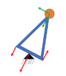
Look at the image below where I've drawn a rigid triangle, with thin lightweight rods and a fixed mass M attached as shown. There is a constant torque (2Fr) applied at a fixed pivot point P bisecting the top rod. Let's assume M is at rest and then a torque is added about pivot point P which will angularly accelerate the triangle and M in a circular path. Lets also assume the triangle is on a frictionless flat table so there is no gravity involved.
1. Am I correct that forces F1 and F2 will act on mass M, with a resultant net tangential force (as shown in image below) when the triangle is at rest?
2. I am assuming that the forces F1 and F2 will remain unchanged when the triangle is angularly accelerating . I've been informed they may change but that doesn't make any sense to me because the torque forces F are constant. There is a push force F1 on M via the left arm and a pull force F2 on M via the right arm. When I add those 2 forces , the resultant force is always tangential to the circular path but where is the centripetal force to keep mass M moving in a circle?
 ##\qquad ## !