Heat Transfer and Time to Reach Steady State

  • Thread starter Thread starter LT72884
  • Start date Start date
Join the discussion
Registration is free. Ask a follow-up in this thread, or start your own.
16 replies · 975 views
LT72884
Messages
341
Reaction score
50
Homework Statement
The surface temp, T1, of the rubber in open air is 330F. The heat travels through the rubber and the backside of the rubber between the composite block hit a steady state T2 temp of 226F. if the T1 heat source of 330F were only applied for 12 hours, IE, I turned on a clothes iron that was in direct contact with the front side of the rubber. At the end of 12 hours, we know T2 is 226F, how long did it take to get to that 226F? HINT: Its not 12 hours nor Infinity. Its between 2-5 hours. This is an actual expierment
Relevant Equations
1D plane wall equations.
Hello All. Hope all is well with the forums. I have conducted a heat transfer lab experiment and i have gotten stuck. Its not complicated, but i am stuck.

I have figured out half of my answers but need help with the second half.

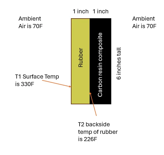
I have a 1 inch thick by 6 inch tall piece of basic rubber (use basic properties from the book or online) and it is attached to a carbon fiber resin block that has the exact same dimensions of 6 inch tall by 1 inch thick. Use properties for the composite block from book or online.

The surface temp, T1, of the rubber is 330F and in open air of the lab (70F). The heat travels through the rubber to the backside of the rubber between the composite block hit a steady state T2 temp of 226F

Here is my question, if the T1 heat source of 330F were only applied for 12 hours, IE, I turned on an iron that was in direct contact with the front side of the rubber. At the end of 12 hours, we know T2 is 226F, BUT how long did it take to get to that 226F? I know the answer is NOT 12 hours, nor is it infinite 🙂 It is somewhere between 3 to 5 hours that it levels out around 226F, BUT I do not know how to calculate that. This is where I need some help.
Thanks for any guidance.
1787512183444.webp
 
Physics news on Phys.org
Can you draw a couple general plots of what you expect the temperature distribution across your materials are at a few instances of time (maybe initially, and some small(ish) time later - assuming 1D conduction) to form some baseline thoughts about how you expect it to behave?
 
Last edited:
Reply
  • Like
Likes   Reactions: LT72884
erobz said:
Can you draw a couple general plots of what you expect the temperature distribution across your materials are at a few instances of time (maybe initially, and some small(ish) time later - assuming 1D conduction) to form some baseline thoughts about how you expect it to behave?
It will look like the graph of a capacitor charge, slowly rising until steady state. So some where between 2 and 5 hours, the T2 temp hits 226 and stays flat the rest of the time until 12 hours is up. I would like to find the time it hits that flat line

1787515779606.webp
 

Attachments

  • 1787515728280.webp
    1787515728280.webp
    5.8 KB · Views: 2
LT72884 said:
It will look like the graph of a capacitor charge, slowly rising until steady state. So some where between 2 and 5 hours, the T2 temp hits 226 and stays flat the rest of the time until 12 hours is up.

View attachment 373809
In order to predict what the temperature is at the rubber/carbon interface at some time after the heat is applied and before steady state is reached you should think about what the temperature plot is spatially across the blocks during that time frame and how they evolve over time, also think about what assumptions you are making (will need to make) to simplify this problem (maybe you will imagine they look like the temp distributions across the walls when the system is at steady state). The equations of heat transfer (conduction across the walls - convection to the surroundings) across the boundaries and through the mediums will govern the outcomes. I'm trying to get you to put a flag in the ground so to speak so you can start to figure out how you might go about making an approximation to how this would behave.
 
Reply
  • Like
Likes   Reactions: LT72884
erobz said:
In order to predict what the temperature is at the rubber/carbon interface at some time after the heat is applied and before steady state is reached you should think about what the temperature plot is spatially across the blocks during that time frame and how they evolve over time, also think about what assumptions you are making (will need to make) to simplify this problem (maybe you will imagine they look like the temp distributions across the walls when the system is at steady state). The equations of heat transfer (conduction across the walls - convection to the surroundings) across the boundaries and through the mediums will govern the outcomes. I'm trying to get you to put a flag in the ground so to speak so you can start to figure out how you might go about making an approximation to how this would behave.
i have no idea.... i just know what the plot looks like. I could divide it into 4 "areas" or points, but then its the same issue, how long does the thermal wave take to get to point 1,2,3,4 etc
 
LT72884 said:
i have no idea.... i just know what the plot looks like. I could divide it into 4 "areas" or points, but then its the same issue, how long does the thermal wave take to get to point 1,2,3,4 etc
Well...at the heart of this question lies the heat equation (a second order partial differential equation) that needs to be solved for your system of "plane walls" of the form ## m c_p\frac{\partial T}{\partial t} = \frac{\partial ^2T}{\partial x^2 }## complete with all the appropriate boundary/initial conditions. Is that ringing a bell in your studies, did the instructors go over this problem and its solution given the boundary/initial conditions?
 
Oh, and just to be clear. As far as I understand this problem it is effectively asking "how long did it take for this plane wall system to reach steady state". At that point in time the thermal gradients are fixed across the materials, and they would just be linear. However, computing the time for which this take is a complicated problem in my opinion because the gradients are non-linear (spatially) (governed by said heat equation above), and continuously changing in time. So does this sound like the level of difficulty you expect to need to answer this question (is your textbook chapter covering transient conduction currently or in the recent past)? If so, we'll have to wait for an expert(in my opinion) to move forward. It would be a lot of effort for me to learn the specifics of this problem, and try to put something analytical together (and it wouldn't be a smooth process).
 
Reply
  • Like
Likes   Reactions: LT72884
erobz said:
Oh, and just to be clear. As far as I understand this problem it is effectively asking "how long did it take for this plane wall system to reach steady state". At that point in time the thermal gradients are fixed across the materials, and they would just be linear. However, computing the time for which this take is a complicated problem in my opinion because the gradients are non-linear (spatially) (governed by said heat equation above), and continuously changing in time. So does this sound like the level of difficulty you expect to need to answer this question (is your textbook chapter covering transient conduction currently or in the recent past)? If so, we'll have to wait for an expert(in my opinion) to move forward. It would be a lot of effort for me to learn the specifics of this problem, and try to put something analytical together (and it wouldn't be a smooth process).
oh dang. No they have not gone over this stuff. This is kind of an "extra" step im taking to learn more... maybe i bit of more than i could chew?

My end goal was to make a simple excel sheet that would calculate the time and make a simple graph, but im thinking this is a bit more complicated.

Heat transfer was last semester, this is now just lab work, and i did the main portion correctly, and now i want to go the extra step but that might not be possible with the knowledge i have.

I tried to use chatgpt and that went nowhere haha
 
LT72884 said:
oh dang. No they have not gone over this stuff. This is kind of an "extra" step im taking to learn more... maybe i bit of more than i could chew?

My end goal was to make a simple excel sheet that would calculate the time and make a simple graph, but im thinking this is a bit more complicated.

Heat transfer was last semester, this is now just lab work, and i did the main portion correctly, and now i want to go the extra step but that might not be possible with the knowledge i have.

I tried to use chatgpt and that went nowhere haha
It's definitely a major jump in mathematical complexity, which is why it's likely glossed over in undergraduate coursework.

So here is what is going on in a single plane wall that is subjects to your conditions:

1787584388976.webp


The purple, yellow, pink curves are ##T(x,t)## at some arbitrary times after the initial state and before steady state is achieved (governed by the heat equation I described above). Your problem actually continues to add complexity as when ##T(x,t)## reaches the boundary ##x=L## the whole thing starts over, but this time it has a boundary condition that depends on ##T(x,t)## itself.

Let me know what you think.

[Mentor Note: post edited to remove AI references]
 
Last edited by a moderator:
Reply
  • Like
Likes   Reactions: LT72884
LT72884 said:
I tried to use chatgpt and that went nowhere haha
Just a reminder that AI is not allowed as a technical reference in the technical forums. :wink:
 
Reply
  • Like
Likes   Reactions: LT72884 and erobz
berkeman said:
Just a reminder that AI is not allowed as a technical reference in the technical forums. :wink:
excellent, i am glad of that. I have not been to these forums for a few years since i have been doing well in school, then heat transfer happened hahaha. I will not mention the forbidden ai
 
Reply
  • Like
Likes   Reactions: berkeman
The question is not well posed. Two pieces of information are missing:
  • the depth of the block (into the page)
  • the granularity of the temperature measurement
In principle, steady state is never reached. What you need to ask is how long before it is near enough to steady state, i.e. how accurately is the temperature to be measured?

If the depth of the block is also 6” or more, the thickness is small relative to the other two dimensions. This allows a rough calculation by taking those 6” dimensions as effectively infinite, which reduces it to a one dimensional heat flow.

There is another complication: the temperature at the far side of the composite block is not fixed, so another equation is needed relating the rate of loss of heat to the emissivity and the ambient temperature. You can deduce the emissivity from the known final state.

Glossing over that complication, the solution to the one dimensional equation takes the form of a sum of terms like ##\Theta=A+Bx+C_ne^{-\lambda_n t}\cos(k_nx)##.
 
Reply
  • Like
Likes   Reactions: LT72884
haruspex said:
The question is not well posed. Two pieces of information are missing:
  • the depth of the block (into the page)
  • the granularity of the temperature measurement
In principle, steady state is never reached. What you need to ask is how long before it is near enough to steady state, i.e. how accurately is the temperature to be measured?

If the depth of the block is also 6” or more, the thickness is small relative to the other two dimensions. This allows a rough calculation by taking those 6” dimensions as effectively infinite, which reduces it to a one dimensional heat flow.

There is another complication: the temperature at the far side of the composite block is not fixed, so another equation is needed relating the rate of loss of heat to the emissivity and the ambient temperature. You can deduce the emissivity from the known final state.

Glossing over that complication, the solution to the one dimensional equation takes the form of a sum of terms like ##\Theta=A+Bx+C_ne^{-\lambda_n t}\cos(k_nx)##.
I did mention 8n my original problem and question that i know its not infinite time, so i would have to pick 99% which is near enough.

The depth of the block is not needed as well

I didn't take measurements at the composite side. But if solving the thermal circuit, i 9nly need to splve for T2, BUT i can see why having that other temp on the composite could help find yhe time it takes to hit 99% of the temp.

I could probably do a basic 1d to find T3. But to do my actual problem, this is looking complicated haha
 
Another parameter in this is the heat transfer coefficient on the far (air) side surface of the composite block. This determines relationship between the heat flux at the surface and the surface temperature.

You also need to take into account the change in slope of T vs x when you cross the interface between the two materials.
 
Reply
  • Like
Likes   Reactions: Lord Jestocost
LT72884 said:
The depth of the block is not needed as well
It is in principle unless the near and far faces are perfectly insulated.
LT72884 said:
if solving the thermal circuit, i 9nly need to splve for T2
The time it takes T2 to reach a particular temperature will depend on the transfer through the composite. You have to model that too.
 
Last edited:
Chestermiller said:
Another parameter in this is the heat transfer coefficient on the far (air) side surface of the composite block. This determines relationship between the heat flux at the surface and the surface temperature.
Yes, I only discussed radiation. So what is the full expression for the rate of loss of heat at the air surface… ##A(T_{block}-T_{air})+\epsilon(T_{block}^4-T_{air}^4)##?
Chestermiller said:
You also need to take into account the change in slope of T vs x when you cross the interface between the two materials.
How so? Isn't it just a matter of two different equations within the blocks with a common boundary value? Why do we care that the gradients are different there?
 
haruspex said:
Yes, I only discussed radiation. So what is the full expression for the rate of loss of heat at the air surface… ##A(T_{block}-T_{air})+\epsilon(T_{block}^4-T_{air}^4)##?
I think we can neglect radiation loss in comparison to convection heat loss, as ## q^{"}_{conv} = h ( T - T_{\infty})## is about an order of magnitude larger than ## q^{"}_{rad} = \sigma \epsilon ( T^4 - T^4_\infty)## using 226 F for ##T##. The far right side will be even cooler during the whole process.
haruspex said:
How so? Isn't it just a matter of two different equations within the blocks with a common boundary value? Why do we care that the gradients are different there?
As far as I can tell it's like you say; The temp ##T(x,t)|_L## just becomes the common boundary condition between the rubber and carbon resin once the heat has passed through the first wall (the total system being of length ##2L##).

Also, at first there is no convective boundary condition on the far right wall. The heat has to propagate through the material 1 and material 2 before a temperature change is able to register on the far right surface ( the materials are absorbing heat and conducting layer by layer toward the right) and heat transfer out of the walls can begin by convection.
 
Last edited: