An iron cylinder inside a solenoid

AI Thread Summary
The discussion revolves around the application of Ampere's Law to analyze the magnetic field in a solenoid containing an iron cylinder. It highlights the complexity of calculating the magnetic field due to the non-uniform nature of the field and the need for accurate measurements of magnetization and magnetic field strength. Participants express concerns about the small values of the magnetic field and the limitations of the problem setup, suggesting that it may not be ideal for analysis. They also note that the magnetization of iron can saturate, complicating the calculations further. Overall, the conversation emphasizes the challenges in accurately modeling magnetic fields in materials like iron within solenoids.
lorenz0
Messages
151
Reaction score
28
Homework Statement
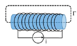
An iron cylinder with section ##S = 10 cm^2## and length ##d = 20 cm## is uniformly magnetized being placed into a solenoid with ##200## turns around the surface of the cylinder and traversed by a current ##i##. The magnetic field that is measured inside the cylinder is ##H = 10^3 A / m## and ##\oint_{\Gamma} \vec{B}\cdot d\vec{l}= 8\cdot 10^{-4} T m##.
Calculate the current ##i## flowing in the circuit and the magnetization vector ##\vec{M}##.
Relevant Equations
##\oint_{\Gamma}\vec{H}\cdot d\vec{l}=\sum I##, ##\vec{H}=\frac{\vec{B}-\mu_0\vec{M}}{\mu_0}##
From ##\oint_{\Gamma}\vec{H}\cdot d\vec{l}=\sum I## by Ampere's Law which gives ##H \Delta l=\Delta N\cdot i\Leftrightarrow H=n i## where ##n=## number of turns per unit length so ##i=\frac{H}{n}=\frac{10^3 A / m}{\frac{200}{0.2m}}=1 A##.

Since ##\vec{H}=\frac{\vec{B}-\mu_0\vec{M}}{\mu_0}## we also get ##\oint_{\Gamma}\vec{H}\cdot d\vec{l}=\frac{1}{\mu_0}\oint_{\Gamma}(\vec{B}-\mu_0\vec{M})\cdot d\vec{l}\Leftrightarrow \oint_{\Gamma}\vec{M}\cdot d\vec{l}=\frac{1}{\mu_0}\oint_{\Gamma}\vec{B}\cdot d\vec{l}-ni\Leftrightarrow M=\frac{1}{\mu_0}\oint_{\Gamma} \vec{B}\cdot d\vec{l}-\frac{n}{l}i=\frac{1}{4\pi\cdot 10^{-7} H/m}\cdot (8\cdot 10^{-4}Tm)-\frac{200}{0.2m}1 A## ... this last part doesn't really convince me, even dimensionally, even if it looks like the initial idea to use Ampere's Law and then make the substitution ##\vec{H}=\frac{\vec{B}-\mu_0\vec{M}}{\mu_0}## does make sense?

Is there a way to amend my work? I would like to understand how to work with magnetic fields in matter like in this case and I would be grateful for an explanation about how to do that. Thanks
 

Attachments

  • iron.png
    iron.png
    12.4 KB · Views: 166
Physics news on Phys.org
This one doesn't seem to be the best problem of this type. The numbers for ## B ## are too small, and both ## H ## and ## B ## will not be constant along the loop ## \Gamma ## shown for the integral. It looks like you computed the current ## i ## correctly, but I don't know that much else can be done with the numbers they give you.

In addition, the magnetic field that gets measured is ## B ##. The "field" ## H ## does not get measured unless you measure ## B ## without the iron in the solenoid. It is also incorrect to say that ## \oint B \cdot dl ## was measured, unless a complete mapping was done.

I don't know of a very good way of treating the finite length iron cylinder inside a solenoid, unless you are given the value of the magnetization ## M ## and or the value of ## B ## in the iron. Writing ##\oint H \cdot dl=NI ## does not lead to a straightforward solution, because ## H ## is very non-uniform. Complex numerical methods using the pole method could be useful, but that is a somewhat advanced treatment of the problem, and would take a lot of work.
 
Last edited:
Charles Link said:
This one doesn't seem to be the best problem of this type. The numbers for ## B ## are too small, and both ## H ## and ## B ## will not be constant along the loop ## \Gamma ## shown for the integral. It looks like you computed the current ## i ## correctly, but I don't know that much else can be done with the numbers they give you.

In addition, the magnetic field that gets measured is ## B ##. The "field" ## H ## does not get measured unless you measure ## B ## without the iron in the solenoid. It is also incorrect to say that ## \oint B \cdot dl ## was measured, unless a complete mapping was done.

I don't know of a very good way of treating the finite length iron cylinder inside a solenoid, unless you are given the value of the magnetization ## M ## and or the value of ## B ## in the iron. Writing ##\oint H \cdot dl=NI ## does not lead to a straightforward solution, because ## H ## is very non-uniform. Complex numerical methods using the pole method could be useful, but that is a somewhat advanced treatment of the problem, and would take a lot of work.
Thanks for your very thorough answer
 
  • Like
Likes Charles Link
I gave it a little more thought: To a somewhat good approximation, you could assume that ## B\approx 0 ## in the exterior part of the loop for the integral. This is not ideal, but it could work for some estimates. In any case, ## B ## in the iron should be in the neighborhood of ## 1 ## T, (considering the value of ## H ## and typical magnetic susceptibility values for iron), so that the integral ## \oint B \cdot dl ## should be about .2 Tm. This is where the problem is really lacking, and without a better number for the integral, it limits us in what we can do with it.
 
Last edited:
It is perhaps worthwhile to mention a couple additional things about this problem. It seems to not be treated in detail in a lot of the E&M textbooks. In the case of iron, such as that which is used in transformers, the hysteresis curve is such that when the applied ## H ## from the solenoid is just slightly negative (approximately zero), the magnetization ## M ## will also be zero. Meanwhile for material that would make a permanent magnet, the applied ## H ## needs to be very large and negative to reverse the direction of magnetization.

One other thing worth mentioning is that the magnetization will saturate in the iron at somewhere around ## \mu_o M=2 ## T. With the numbers that were given here for ## H ##, I believe the ## M ## would be rather close to saturation, rather than giving a number that they gave for ## \oint B \cdot dl ## of ## 8E-4 ## with an ## L=.2 ##.

The available literature on the subject of permanent magnets as well as the case of iron in a solenoid that makes an electromagnet seems to have improved in the last couple of years, but previous to that, it seemed to be rather deficient.
 
Thread 'Minimum mass of a block'
Here we know that if block B is going to move up or just be at the verge of moving up ##Mg \sin \theta ## will act downwards and maximum static friction will act downwards ## \mu Mg \cos \theta ## Now what im confused by is how will we know " how quickly" block B reaches its maximum static friction value without any numbers, the suggested solution says that when block A is at its maximum extension, then block B will start to move up but with a certain set of values couldn't block A reach...
TL;DR Summary: Find Electric field due to charges between 2 parallel infinite planes using Gauss law at any point Here's the diagram. We have a uniform p (rho) density of charges between 2 infinite planes in the cartesian coordinates system. I used a cube of thickness a that spans from z=-a/2 to z=a/2 as a Gaussian surface, each side of the cube has area A. I know that the field depends only on z since there is translational invariance in x and y directions because the planes are...
Thread 'Calculation of Tensile Forces in Piston-Type Water-Lifting Devices at Elevated Locations'
Figure 1 Overall Structure Diagram Figure 2: Top view of the piston when it is cylindrical A circular opening is created at a height of 5 meters above the water surface. Inside this opening is a sleeve-type piston with a cross-sectional area of 1 square meter. The piston is pulled to the right at a constant speed. The pulling force is(Figure 2): F = ρshg = 1000 × 1 × 5 × 10 = 50,000 N. Figure 3: Modifying the structure to incorporate a fixed internal piston When I modify the piston...
Back
Top