Mech_LS24
- 148
- 16
Summary:: Calculate the torque needed to move a load with a lead screw. Torque is needed in order to find the right DC motor and coupling.
Hello,
I have a design with using a lead screw to move a load (see sketch below). The load will operate in both directions, in order to select the right DC motor and coupling (flexible coupling) I want to calculate how many torque is needed to move the load (for both directions. I found out the following and hope I am on the right way:
Calculation:

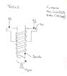
Sketch:

Hello,
I have a design with using a lead screw to move a load (see sketch below). The load will operate in both directions, in order to select the right DC motor and coupling (flexible coupling) I want to calculate how many torque is needed to move the load (for both directions. I found out the following and hope I am on the right way:
- Material nut = CuSn7ZnPb (Bronze)
- Material spindle = C45 (Steel)
- Friction for Steel/Bronze according Shigley = 0.2
- Load (F) = 1000 N = 1000/2 = 500 N
- Spindle and nut are Tr12 x 2
Calculation:
Sketch: