AyVent
- 1
- 0
- TL;DR
- I am building an experimental closed RAS. However, despite my best efforts, I faced issues with the pump/venturi calibration. The system will need plumbing changes but I need advice to plan the best course of action. Help is greatly appreciated.
Hello,
I am building an experimental closed RAS. However, despite my best efforts, I faced issues with the pump/venturi calibration. The system will need plumbing changes but I need advice to plan the best course of action. Help is greatly appreciated.
Here is an overview of the system:
The cycle goes like this: sump tank> pump> venturi (air)> oxygen saturator> tank> sump tank
Sump tank: a standard 1m3 cylindrical PE tank buried about 90 cm underground with about 30 cm aboveground. Inlet to the pump is an inverted L shaped 1 inch PE pipe with check valve installed.
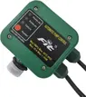
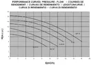
Pump: 1/3 hp pool pump with a low head high flow curve. Currently one is installed but plan was two in parallel. It also has an automatic pump control (APC) to protect from dry-run and heating issues. (Both attached)
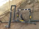
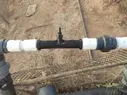
Venturi: Mazzei 1584-A PP (attached)
Oxygen Saturator: design followed as is from a SARE project results ( https://projects.sare.org/project-reports/fnc20-1207/ ) (also attached)
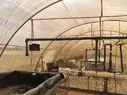
Tank: h: 0.65 m L: 27m W: 2.4m; an open inlet pouring down 1.3m above tank level with an overflow 4 inch outlet at around 0.58m height. (some system pictures are attached)
My issue is that the APC keeps cutting off the pump a few secs after operation. I tested the pump using a hose and it worked normally. There were leaks close to the venturi and they were fixed. But I suspect they might be leaking air still. I then reviewed the Head calculation of both the system and the pump.
System Head was around 4m and the pump curve starts at 4m Head at max flow. So, I tried to adjust the valves until the Head was workable or comfortable for the pump. And it worked with all valves mostly closed but I shut it down after 20-30 mins. After a couple tries of this, it just wasn’t consistent to get it to work this way. And the venturi was blowing bubble at this state. No suction at all. Tbh, I originally designed the piping for future expansion and the resulting increase in flows but this caused issues.
Aside from obviously increasing the system head, what steps do you think should be done to test for and modify to ensure normal operation?
Excuse the rough work, I am from a business background but with a certificate in RAS from Cornell.
And again, thanks for all the help.
I am building an experimental closed RAS. However, despite my best efforts, I faced issues with the pump/venturi calibration. The system will need plumbing changes but I need advice to plan the best course of action. Help is greatly appreciated.
Here is an overview of the system:
The cycle goes like this: sump tank> pump> venturi (air)> oxygen saturator> tank> sump tank
Sump tank: a standard 1m3 cylindrical PE tank buried about 90 cm underground with about 30 cm aboveground. Inlet to the pump is an inverted L shaped 1 inch PE pipe with check valve installed.
Pump: 1/3 hp pool pump with a low head high flow curve. Currently one is installed but plan was two in parallel. It also has an automatic pump control (APC) to protect from dry-run and heating issues. (Both attached)
Venturi: Mazzei 1584-A PP (attached)
Oxygen Saturator: design followed as is from a SARE project results ( https://projects.sare.org/project-reports/fnc20-1207/ ) (also attached)
Tank: h: 0.65 m L: 27m W: 2.4m; an open inlet pouring down 1.3m above tank level with an overflow 4 inch outlet at around 0.58m height. (some system pictures are attached)
My issue is that the APC keeps cutting off the pump a few secs after operation. I tested the pump using a hose and it worked normally. There were leaks close to the venturi and they were fixed. But I suspect they might be leaking air still. I then reviewed the Head calculation of both the system and the pump.
System Head was around 4m and the pump curve starts at 4m Head at max flow. So, I tried to adjust the valves until the Head was workable or comfortable for the pump. And it worked with all valves mostly closed but I shut it down after 20-30 mins. After a couple tries of this, it just wasn’t consistent to get it to work this way. And the venturi was blowing bubble at this state. No suction at all. Tbh, I originally designed the piping for future expansion and the resulting increase in flows but this caused issues.
Aside from obviously increasing the system head, what steps do you think should be done to test for and modify to ensure normal operation?
Excuse the rough work, I am from a business background but with a certificate in RAS from Cornell.
And again, thanks for all the help.
Attachments
-
 APC.webp20.8 KB · Views: 42
 -
 astral-sena-pump.webp33 KB · Views: 43
 -
Mazzei Venturi Table_GAS-SUCTION2018-07-05.pdf992.9 KB · Views: 23
-
Venturi and staturator design.pdf80.9 KB · Views: 59
-
 Overview 1.webp130.1 KB · Views: 27
 -
 Overview 2.webp156.7 KB · Views: 54
 -
 Venturi piping.webp138.7 KB · Views: 44
 -
 Venturi.webp112.5 KB · Views: 35
 -
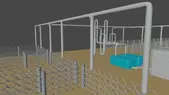 3D of planned design prototype.webp42.6 KB · Views: 32