Can You Derive the Gain Equation for a Non-Ideal Op Amp?

  • Thread starter Thread starter GRW
  • Start date Start date
  • Tags Tags
    Amp Op amp
Join the discussion
Registration is free. Start your own thread to ask a follow-up.
11 replies · 3K views
GRW
Messages
5
Reaction score
0
[ mod note: thread title corrected ][/color]

Hi All,

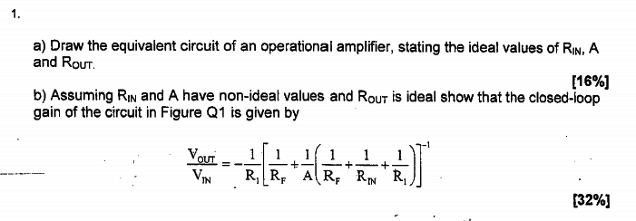
My first post in the forums, hopefully I'll be able to give out as much help as I receive. I'm currently stuck on an Op Amp gain derivation.

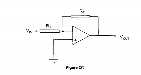
Attached is the question and diagram, the derivation I am struggling with is part B.

I understand the gain for this Op Amp were it ideal would be 1+ Rf/R1 but I cannot seem to derive the equation if the input resistance is not ideal.

Thanks in advance,

George

Capture2.PNG
Capture.PNG
 
Last edited by a moderator:
Physics news on Phys.org
Hi GRW. :welcome:

You won't be able to derive the equation in (b) until you have completed part (a), drawing the equivalent circuit with ideal components.
 
Thanks for your reply Nascent,

I have already completed part A but I can't see how is it that relevant to part B? I know the equivalent circuit and that Rin is in the Op Amp internally and that A is the Op Amp gain.

Any further guidance on how the two relate / where to start with part B would be much appreciated.
 
Can you attach your completed circuit diagram for (a), with RI and RF arranged around it as in Fig Q1.
 
Sorry but I don't have any way of uploading my paper working to a computer. It is as in Fig 1, with Rin linked between the + and - terminals of the Op Amp.
 
GRW said:
Sorry but I don't have any way of uploading my paper working to a computer. It is as in Fig 1, with Rin linked between the + and - terminals of the Op Amp.
That is the circuit you analyze, but this time without a reliance on the dodge of a "virtual earth".
 
It's the circuit analysis for the derivation here that I am struggling with. Sorry if my initial explanation was poor.
 
You draw a large circuit diagram. Mark vin. Label the voltage at the input to the amplifier proper, at the junction of the 3 resistances, I called it va.

How will you label the output of the amplifier?
 
GRW said:
[ mod note: thread title corrected ]

Hi All,

My first post in the forums, hopefully I'll be able to give out as much help as I receive. I'm currently stuck on an Op Amp gain derivation.
Attached is the question and diagram, the derivation I am struggling with is part B.
I understand the gain for this Op Amp were it ideal would be 1+ Rf/R1 but I cannot seem to derive the equation if the input resistance is not ideal.
Thanks in advance
George

View attachment 86256View attachment 86255

Question to you: The input voltage is connected (via a resistor) to the inverting terminal of the opamp. Wouldn`t you expect a negative gain in this case?
(Your ideal gain value (1+Rf/R1) is not correct!)
You have stated: "I understand that the gain ...".
Did you really "understand"? I don`t hope that you understood a false result! That would be fatal!.
 
Last edited:
a) This you must draw on your own. If you could somehow take a picture and upload it, we could verify if it is correct. What do you think the ideal values for ##A##, ##R_{in}##, and ##R_{out}## are? Hint: Think about preserving the signal. Do you need a large input impedance or a small one?

b) For the closed loop gain, what equation is relevant to op-amp operation? Use this equation, and the virtual ground between ##R_1## and ##R_F##.
 
Thanks for all your help guys, after a decent sleep last night I woke up this morning and after re reading the suggestions I was able to derive it no trouble. Thanks again and I look forward to being part of the forum!
GRW
 
GRW said:
Thanks for all your help guys, after a decent sleep last night I woke up this morning and after re reading the suggestions I was able to derive it no trouble. Thanks again and I look forward to being part of the forum!
GRW
GRW, to be honest - did you derive the correct result really without any help?