MarkTheQuark
- 5
- 2
- TL;DR
- Impedancy Spectroscopy
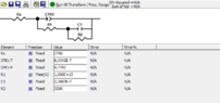
I did a few experiments recently of impedance spectroscopy, and I've gathered some data that i'm having some issues to find an equivalent circuit that can fit the data.
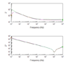
The equivalent circuit that I've got, it's pretty similar with the data (graph and circuit below)
But the problem is, at low frequencies, my data values drop, while the fit from the circuit keeps going up.
Z' represents the real part from the impedance, so basically I need to my equivalent circuit to drop the resistance at low frequencies.
What circuit element, or what I could do, so that I could find an equivalent circuit to my data?