COG calculation of diffracted spots on a camera

Click For Summary
SUMMARY

The discussion focuses on simulating the Center of Gravity (COG) calculation for diffracted spots on a camera sensor, specifically using parameters such as a camera pixel size of 4um, a gap size of 100nm, and a camera resolution of 4000 x 4000 pixels. The simulation aims to account for photon noise modeled by a Poisson distribution and read-out noise as zero mean normal noise, utilizing Monte Carlo simulations with 500 random realizations. Participants suggest using equations for the Airy disk or Gaussian functions to model the diffracted spots and propose creating a correction matrix to adjust COG calculations affected by sensor edge effects.

PREREQUISITES
  • Understanding of diffraction patterns and their relation to aperture size
  • Familiarity with Monte Carlo simulation techniques
  • Knowledge of MATLAB for coding simulations
  • Basic concepts of sampling theory and COG calculations
NEXT STEPS
  • Implement a MATLAB script for simulating diffracted spots using the Airy disk equation
  • Research methods for creating correction matrices in COG calculations
  • Explore advanced noise modeling techniques for sensor data
  • Learn about 2D sampling theory and its implications for sensor design
USEFUL FOR

This discussion is beneficial for optical engineers, camera system designers, and researchers in imaging science who are focused on improving the accuracy of COG calculations in sensor applications.

Gifty01
Messages
11
Reaction score
0
TL;DR
COG calculation of diffracted spots on a camera
Hi all,

I will like to simulate diffracted spots at least two spots, on a camera. I will be glad if someone can help out with a code. below are the details required:
camera pixel size = 4um (each pixel can be sub divided for better calculation), gap size = 100nm, camera length = 4000 x 4000 pixels, diffracted spot size on the camera = 30 um (airy disk eqn or gaussion eqn can be used to simulate the diffracted spot), photon noise = poisson distribution, read out noise = zero mean normal noise, monte-carlo simulation = 500 random realizations. Other details if needed are:
saturation capacity = 10300, QE = 68%, SNR =6.7 bit.
1634533214104.png
Eqn for COG calculation

At each iterations, the true center is placed randomly within the CCD pixel and then compared to the measured center.

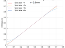
A graph of Center of gravity (COG) against spot positioning (i.e moved across the sensor from left to right) should be calculated. A sample of how the plot will look like is attached.
1634533673735.png

Due to effect of sensor edge, the COG calculation deflects from the real value. I will like to create a matrix which corrects the COG calculation by subtracting e.g at the left edge of the edge, and adding up e,g at the other edge to the right. since the measured COG value is known. Thanks in advance.
 

Attachments

  • 1634533622564.png
    1634533622564.png
    11.1 KB · Views: 192
Astronomy news on Phys.org
Gifty01 said:
Summary:: COG calculation of diffracted spots on a camera

I will like to simulate diffracted spots at least two spots, on a camera.
Not quite sure what you mean. Is the diffraction pattern due to the diameter of the optics? If so, then the output of a sensor pixel will be a rectangular / square sample in 2D.

In terms of basic ideas on sampling theory. Just working on one dimension, for a start (imagining a long, narrow sensor element), the output level on the sensor pixel will be the integral of the diffraction pattern between the limits of the sensor width. If you were to scan the sensor across the image, you would get a low pass filtered (smoothed) version of the original pattern.
 
Thanks for your response sophiecentaur. The diffraction is due to the size of the aperture. I am not so good in coding. I wrote a bad code with MATLAB which takes a lot of time to run completely. the graph showing the plot of COG against spot position was the plot I obtained, which shows that there is much deviation of the spot position and the calculated COG, which is due to the finiteness of the pixel or sensor (since we used a finite sensor to sample a continuous function in this case the airy disk). That was why I am trying to obtain a matrix that could be added to effectively calculate the COG so as to get rid of the sensor edge effect. Thanks.
 
Gifty01 said:
I am not so good in coding.
Practice makes perfect. It is ages since I did anything more than formulae in Excel.
Your problem could be straightforward - certainly it is in one dimension. That's just like the simple moments calculations.
if M is the total mass of a line of small masses m0 m1, m2 ...mn and they are spaced by d, the basic 'school' method to find the position x of M from one end of the row is:
M.x = d.m1 + 2d.m2 + 3d.m3 + 4d.m4 . . .etc . . .
In 2D, your m values would be the sum of the my 's on either side of the position of the max of the mx 's. It will give you a corrected x position for the CM to somewhere to one side of the chosen maximum. If you get several equal values of m, you can use the first and the correction will take care of it. In fact you can take any starting point but you wouldn't want to use too big a range or you could catch two stars.
If that makes sense then you can do the same for the y distances in the array.
There may be better approaches but I could code that without too much trouble
I just looked on Google and found this which does just what I said.
 

Similar threads

  • · Replies 9 ·
Replies
9
Views
2K
  • · Replies 4 ·
Replies
4
Views
16K
  • · Replies 1 ·
Replies
1
Views
2K
  • · Replies 152 ·
6
Replies
152
Views
11K
  • · Replies 7 ·
Replies
7
Views
5K
  • · Replies 2 ·
Replies
2
Views
7K