Continuously Variable Transmission Idea
- Topic: Automotive
- Thread starter rajava007
- Start date
Join the discussion
Registration is free. Ask a follow-up in this thread, or start your own.
69 replies · 11K views
Physics news on Phys.org
Science Advisor
2025 Award
- 17,264
- 10,726
Then present a set of simple equations that describes your model.A.T. said:I have the real physical thing, and reality says your analysis is wrong.
There needs to be two components with specified angular velocity to constrain the mechanical system.
Science Advisor
- 3,648
- 10,069
The equations governing this gear set seem pretty simple to me. There are four of them:
The gear ratio of the left gear set (##GR_L##), relating angular velocities (##\omega##) of the input (##i##) and output (##o##) shafts:
$$GR_L = \frac{\omega_{oL}}{\omega_{iL}}$$
The gear ratio of the right gear set (##GR_R##), relating angular velocities of the input (##i##) and output (##o##) shafts:
$$GR_R = \frac{\omega_{oR}}{\omega_{iR}}$$
The relationship between the angular velocities of the input differential:
$$\omega_{in} = \frac{\omega_{iL} + \omega_{iR}}{2}$$
The relationship between the angular velocities of the output differential:
$$\omega_{out} = \frac{\omega_{oL} + \omega_{oR}}{2}$$
Already, we can tell we have a problem because we have 4 equations and 5 unknowns (##\omega_{iL}##, ##\omega_{iR}##, ##\omega_{oL}##, ##\omega_{oR}##, ##\omega_{out}##).
For the overall gear ratio (##GR##), it is defined as:
$$GR = \frac{\omega_{out}}{\omega_{in}} = \frac{\omega_{oL} + \omega_{oR}}{\omega_{iL} + \omega_{iR}}=\frac{\omega_{iL}GR_L + \omega_{iR}GR_R}{\omega_{iL} + \omega_{iR}}$$
From that simple equation, we can already define simple - and very intuitive - solutions:
We can define a new constraint, for example ##\frac{\omega_{iR}}{\omega_{in}}##, and the overall gear ratio becomes:
$$GR = \left(1-\frac{1}{2}\frac{\omega_{iR}}{\omega_{in}}\right)GR_L + \frac{1}{2}\frac{\omega_{iR}}{\omega_{in}}GR_R$$
The previous simple solutions become:
The gear ratio of the left gear set (##GR_L##), relating angular velocities (##\omega##) of the input (##i##) and output (##o##) shafts:
$$GR_L = \frac{\omega_{oL}}{\omega_{iL}}$$
The gear ratio of the right gear set (##GR_R##), relating angular velocities of the input (##i##) and output (##o##) shafts:
$$GR_R = \frac{\omega_{oR}}{\omega_{iR}}$$
The relationship between the angular velocities of the input differential:
$$\omega_{in} = \frac{\omega_{iL} + \omega_{iR}}{2}$$
The relationship between the angular velocities of the output differential:
$$\omega_{out} = \frac{\omega_{oL} + \omega_{oR}}{2}$$
Already, we can tell we have a problem because we have 4 equations and 5 unknowns (##\omega_{iL}##, ##\omega_{iR}##, ##\omega_{oL}##, ##\omega_{oR}##, ##\omega_{out}##).
For the overall gear ratio (##GR##), it is defined as:
$$GR = \frac{\omega_{out}}{\omega_{in}} = \frac{\omega_{oL} + \omega_{oR}}{\omega_{iL} + \omega_{iR}}=\frac{\omega_{iL}GR_L + \omega_{iR}GR_R}{\omega_{iL} + \omega_{iR}}$$
From that simple equation, we can already define simple - and very intuitive - solutions:
- if ##\omega_{iR} = 0##, then ##GR = GR_L##;
- if ##\omega_{iL} = \omega_{iR}##, then ##GR = \frac{GR_L + GR_R}{2}##
- if ##\omega_{iL} = 0##, then ##GR = GR_R##;
We can define a new constraint, for example ##\frac{\omega_{iR}}{\omega_{in}}##, and the overall gear ratio becomes:
$$GR = \left(1-\frac{1}{2}\frac{\omega_{iR}}{\omega_{in}}\right)GR_L + \frac{1}{2}\frac{\omega_{iR}}{\omega_{in}}GR_R$$
The previous simple solutions become:
- if ##\frac{\omega_{iR}}{\omega_{in}}= 0##, then ##GR = GR_L##;
- if ##\frac{\omega_{iR}}{\omega_{in}} = 1##, then ##GR = \frac{GR_L + GR_R}{2}##
- if ##\frac{\omega_{iR}}{\omega_{in}} = 2##, then ##GR = GR_R##;
Science Advisor
- 13,482
- 4,352
Seems like I gave up too early. But the insistence of @Baluncore made me more do more careful testing. And it looks like ratios other then 1:1 are indeed possible. Thanks and apologies to @Baluncore.A.T. said: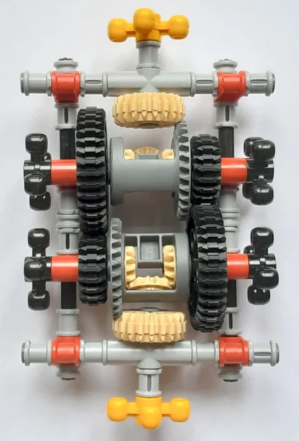
Disappointingly it was exactly what I initially expected: A boring 1:1 transmission that merely reverses the direction (the yellow crosses rotate opposite to each other).
This part however is correct, and consistent with the formulas posted above by @jack action :
It was referring to this idea:A.T. said:Contrary to some claims in this thread, it is not possible to hold the output static, while turning the input continuously.
As @jack action derived above, one can fix the left or right side gears to switch the total gear ratio between minimum and maximum, given by the opposite side gears respectively. But you cannot hold the output static, while the input rotates, because the the total gear ratio can only be varied within a finite range.Halc said:One can for instance bolt the output to a wall, preventing any rotation. The input can still turn freely.
Science Advisor
2025 Award
- 17,264
- 10,726
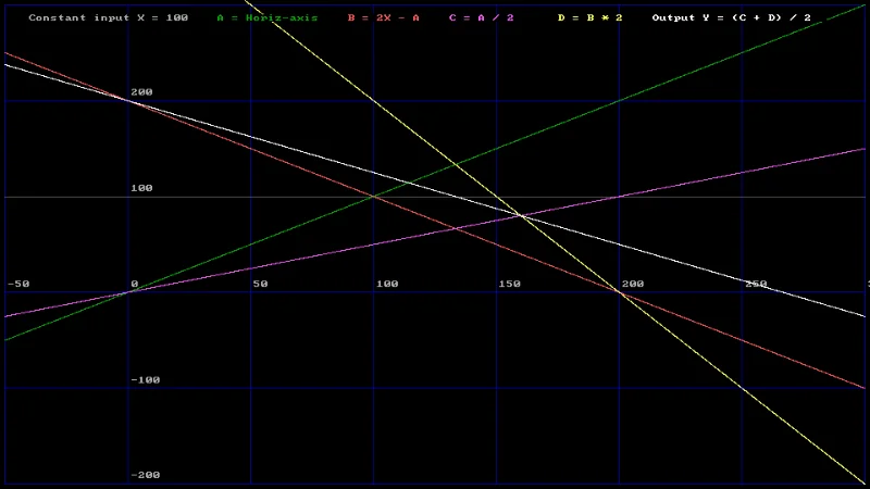
Here is a table that gives the speed of the shafts, all referenced to an input of 100. A and B are the input shaft gears, the average of A and B is X, the input. C and D are the output gears, the average of C and D is Y, the output. These definitions are compliant with those of jack action.
Here is the graph that shows gear ratio. The input X remains at 100%, the output is Y, the bright white trace, that can be read off as % gear ratio.
Code:
    X         A         B         C         D         Y
  100.000   -50.000   250.000   -25.000   500.000   237.500
  100.000   -33.333   233.333   -16.667   466.667   225.000
  100.000   -16.667   216.667    -8.333   433.333   212.500
  100.000     0.000   200.000     0.000   400.000   200.000
  100.000    16.667   183.333     8.333   366.667   187.500
  100.000    33.333   166.667    16.667   333.333   175.000
  100.000    50.000   150.000    25.000   300.000   162.500
  100.000    66.667   133.333    33.333   266.667   150.000
  100.000    83.333   116.667    41.667   233.333   137.500
  100.000   100.000   100.000    50.000   200.000   125.000
  100.000   116.667    83.333    58.333   166.667   112.500
  100.000   133.333    66.667    66.667   133.333   100.000
  100.000   150.000    50.000    75.000   100.000    87.500
  100.000   166.667    33.333    83.333    66.667    75.000
  100.000   183.333    16.667    91.667    33.333    62.500
  100.000   200.000     0.000   100.000     0.000    50.000
  100.000   216.667   -16.667   108.333   -33.333    37.500
  100.000   233.333   -33.333   116.667   -66.667    25.000
  100.000   250.000   -50.000   125.000  -100.000    12.500
  100.000   266.667   -66.667   133.333  -133.333     0.000
  100.000   283.333   -83.333   141.667  -166.667   -12.500
  100.000   300.000  -100.000   150.000  -200.000   -25.000
Science Advisor
2025 Award
- 17,264
- 10,726
Look at the graph, or the table. The output, Y, crosses zero when;A.T. said:But you cannot hold the output static, while the input rotates, because the the total gear ratio can only be varied within a finite range.
X=100.0; A=266.7; B=-66.667; C=133.3; D=-133.3; Y=0.000
You can do that by clamping the output while turning the input. It is not however possible to brake gears to achieve Y≤0, since the speed of A must be accelerated, while the direction of gear B must be reversed. Reversal is not possible with a brake. Only ratios by a factor of two, between 200% and 50% are possible using brakes.
Science Advisor
- 13,482
- 4,352
Is is possible to achieve Y=0 with a single (non zero) input X (all side axles spin freely) just by changing/reversing the gear ratios (AC and BD)? Or do you have to drive some side axles at a given speed for that?Baluncore said:Look at the graph, or the table. The output, Y, crosses zero when;
X=100.0; A=266.7; B=-66.667; C=133.3; D=-133.3; Y=0.000
You can do that by clamping the output while turning the input. It is not however possible to brake gears to achieve Y≤0, since the speed of A must be accelerated, while the direction of gear B must be reversed. Reversal is not possible with a brake. Only ratios by a factor of two, between 200% and 50% are possible using brakes.
Last edited:
Science Advisor
2025 Award
- 17,264
- 10,726
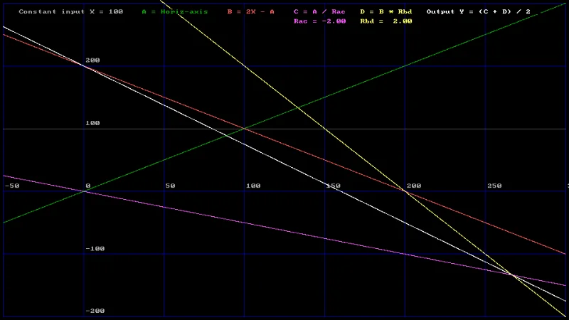
It is not possible to drive Y to zero, unless you brake Y itself. No matter how I juggle the ratios, one of the input gears must be driven negative to have Y = 0.
However, it can be achieved with a reversal, by inserting an idler gear into one, or the other gear train. It is then possible using a brake to have a bidirectional output that can be zero.
Here is a plot with one negative ratio coefficient.
Notice how A and B are positive, while Y can be negative.
However, it can be achieved with a reversal, by inserting an idler gear into one, or the other gear train. It is then possible using a brake to have a bidirectional output that can be zero.
Here is a plot with one negative ratio coefficient.
Notice how A and B are positive, while Y can be negative.
Science Advisor
- 3,648
- 10,069
You can hold the output static by setting ##GR=0##:
$$0 = \left(1-\frac{1}{2}\frac{\omega_{iR}}{\omega_{in}}\right)GR_L + \frac{1}{2}\frac{\omega_{iR}}{\omega_{in}}GR_R$$
$$\frac{1}{2}\frac{\omega_{iR}}{\omega_{in}}GR_L - GR_L = \frac{1}{2}\frac{\omega_{iR}}{\omega_{in}}GR_R$$
$$\frac{1}{2}\frac{\omega_{iR}}{\omega_{in}}(GR_L - GR_R) = GR_L$$
Or:
$$\frac{\omega_{iR}}{\omega_{in}} = \frac{2GR_L}{GR_L - GR_R}$$
Using the other equation:
$$0 = \frac{\omega_{iL}GR_L + \omega_{iR}GR_R}{\omega_{iL} + \omega_{iR}}$$
$$\omega_{iL}GR_L = - \omega_{iR}GR_R$$
$$\frac{\omega_{iL}}{\omega_{iR}} = - \frac{GR_R}{GR_L}$$
So whatever direction you end up on one side, the other side will rotate in reverse.
Also, since power has to be conserved, at least one of the shafts becomes the output if the friction is not enough.
$$0 = \left(1-\frac{1}{2}\frac{\omega_{iR}}{\omega_{in}}\right)GR_L + \frac{1}{2}\frac{\omega_{iR}}{\omega_{in}}GR_R$$
$$\frac{1}{2}\frac{\omega_{iR}}{\omega_{in}}GR_L - GR_L = \frac{1}{2}\frac{\omega_{iR}}{\omega_{in}}GR_R$$
$$\frac{1}{2}\frac{\omega_{iR}}{\omega_{in}}(GR_L - GR_R) = GR_L$$
Or:
$$\frac{\omega_{iR}}{\omega_{in}} = \frac{2GR_L}{GR_L - GR_R}$$
Using the other equation:
$$0 = \frac{\omega_{iL}GR_L + \omega_{iR}GR_R}{\omega_{iL} + \omega_{iR}}$$
$$\omega_{iL}GR_L = - \omega_{iR}GR_R$$
$$\frac{\omega_{iL}}{\omega_{iR}} = - \frac{GR_R}{GR_L}$$
So whatever direction you end up on one side, the other side will rotate in reverse.
Also, since power has to be conserved, at least one of the shafts becomes the output if the friction is not enough.
rajava007
- 9
- 13
Thank you everyone for helping me with this question. It originally started with the fantasy of discovering a new CVT concept, however along the way I learned many new things! Once again I thank you all!
Similar threads
- ZenonDorin
- · Replies 11 ·
- Mechanical Engineering
- Replies
- 11
- kandelabr
- · Replies 9 ·
- Mechanical Engineering
- Replies
- 9