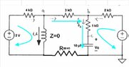
Derive the governing equation for the voltage Vc across the capacitor

In summary: Can you explain explicitly? I still believe there can be current from a to b...There is no potential difference between a and b if the two circuits are not connected to the same ground.
  • #1
annamal
381
33
Homework Statement
Derive the governing equation for the voltage Vc across the capacitor
Relevant Equations
KCL and KVL
I was thinking about doing KVL around the circuit at the right but I noticed when the switch opens, the current through the circuit at the right is not the same throughout
-5 + Ic*2*1-^3 + Ic*10^3 = -Vc

Ic is not the same around the right circuit so I am stuck....

Screenshot 2023-04-23 at 4.41.25 PM.png
 
Physics news on Phys.org
  • #2
Hi,

I suppose you did part a and you have ##V_c## and ##I_L## at ##t\uparrow\infty## ?

annamal said:
-5 + Ic*2*1-^3 + Ic*10^3 = -Vc
Care to explain this ? In particular the second term ?
I can't even read it " ##I_c * 2 * 1 - ?^3 ## "?
Do you mean ##I_{b_2} * 2\ k\Omega## ?

I also think you need some more relevant equations ...

##\ ##
 
  • #3
BvU said:
I suppose you did part a and you have Vc and IL at t↑∞ ?
Please note that the problem is oddly stated and the time of interest (steady state) is t <0.
 
  • #4
hutchphd said:
Please note that the problem is oddly stated and the time of interest (steady state) is t <0.
I agree.
 
  • #5
BvU said:
Hi,

I suppose you did part a and you have ##V_c## and ##I_L## at ##t\uparrow\infty## ?Care to explain this ? In particular the second term ?
I can't even read it " ##I_c * 2 * 1 - ?^3 ## "?
Do you mean ##I_{b_2} * 2\ k\Omega## ?

I also think you need some more relevant equations ...

##\ ##
Yeah, I meant KVL:
-5 + Ic*2*10^3 + Ic*10^3 = -Vc

I know what part a is. I am wondering about part b.
 
  • #6
So the 1 and 2 ##k\Omega## resistors have the same current ?

And do you mean ##I_c = I_{b_2} ## ?

##\ ##
 
  • #7
BvU said:
So the 1 and 2 ##k\Omega## resistors have the same current ?

And do you mean ##I_c = I_{b_2} ## ?

##\ ##
I don't know if the resistors have the same current -- that is just an attempt of mine. In fact I think the resistors might have different current.
 
  • #8
Backing up: do you have ##V_C## and ##I_L## for ##t<0## ?
And for ##t\uparrow\infty## ?

##\ ##
 
  • #9
BvU said:
Backing up: do you have ##V_C## and ##I_L## for ##t<0## ?
And for ##t\uparrow\infty## ?

##\ ##
I only know Vc = 3 V; I_L =0.0015 A for t < 0
 
  • #10
Agreed. Now, when the switch is opened, can there still be a current through the 3 ##k\Omega## ?

##\ ##
 
  • #11
BvU said:
Agreed. Now, when the switch is opened, can there still be a current through the 3 ##k\Omega## ?

##\ ##
I think it can though...why can it not?
 
  • #12
Wouldn't the left circuit and the right circuit be isolated from each other ?

1682344794325.png


(thought experiment: imagine the 2 mH wasn't an inductor but a resistor)

##\ ##
 
  • #13
BvU said:
Wouldn't the left circuit and the right circuit be isolated from each other ?

View attachment 325426

(thought experiment: imagine the 2 mH wasn't an inductor but a resistor)

##\ ##
I still don't understand why the current in the middle is zero....if I do KCL at point a or b, it seems like there could be current there....
 
  • #14
annamal said:
I still don't understand why the current in the middle is zero....if I do KCL at point a or b, it seems like there could be current there....
Like here
1682345972722.png
?

##\ ##
 
  • #15
BvU said:
Like here
View attachment 325428 ?

##\ ##
Can you explain explicitly? I still believe there can be current from a to b...
 
  • #16
There is no potential difference between a and b if the two circuits are not connected to the same ground.

[edit] or do KVL for each of the loops ....
 
  • #17
A circuit is called a circuit because there is a return path that completes the circle.
Without the return path, there can be no current in R=3k.
The value of R=3k becomes irrelevant and may as well be a short circuit.
Nodes a and b will then have the same voltage.
 
  • Like
Likes BvU
  • #18
Baluncore said:
A circuit is called a circuit because there is a return path that completes the circle.
Without the return path, there can be no current in R=3k.
The value of R=3k becomes irrelevant and may as well be a short circuit.
Nodes a and b will then have the same voltage.
I don't understand. I drew the circle and currents in blue below:
1682344794325.png
 
  • #19
annamal said:
I don't understand. I drew the circle and currents in blue below:
Would you expect a light globe to work if you only connected one wire to the battery?
 
  • #20
Another tack: what do you find for ##V_C## and ##I_L## for ##t>>0## ?

##\ ##
 
  • #21
First, if the start process is finished the current through L will be d.c. that means ω=2*π*f=0 then the voltage drop through L will be 0.

On the capacitor eventually, after infinite time, the current will be 0 since Zcap=1/ ω/cap and if ω=0 Zcap=∞

Second, if sw1 is open that it is like instead sw1 a resistance of ∞ ohms is inserted here. So, in the loop between a and b the current it is total voltage drop [what ever it is] in the loop divided by ∞ [no current will flow here].
 

Attachments

  • Infinite resistance.jpg
    Infinite resistance.jpg
    24 KB · Views: 57
  • #22
By-the-way, if between two points in a circuit the voltage drop is 0 then the potential V1=V2. The voltage drop =Z*I. If Z=0 or I=0 the voltage drop is 0.:smile:
 
  • #23
It is not so complicate. You have to find Vc=-(5-Vo)*e^(-γ*t)+5 like formula where Vo it is Vc before sw1 opening.
 

1. What is the governing equation for the voltage Vc across the capacitor?

The governing equation for the voltage Vc across the capacitor is Vc = Q/C, where Q is the charge on the capacitor and C is the capacitance.

2. How is the governing equation derived?

The governing equation is derived from the fundamental relationship between charge and voltage in a capacitor, Q = CV, where Q is the charge, C is the capacitance, and V is the voltage. By rearranging this equation, we get V = Q/C, which is the governing equation for Vc.

3. What are the units of the governing equation for Vc?

The units of the governing equation for Vc are volts (V), as voltage is measured in volts and charge is measured in coulombs (C). The units of capacitance are farads (F), so the final unit for Vc is V/F.

4. Can the governing equation be used for all types of capacitors?

Yes, the governing equation Vc = Q/C can be used for all types of capacitors, as long as the capacitance remains constant. However, for certain types of capacitors, such as non-ideal capacitors, there may be additional factors that need to be taken into account in the equation.

5. How is the governing equation for Vc related to the behavior of a capacitor in a circuit?

The governing equation for Vc relates the voltage across a capacitor to the amount of charge stored on it. In a circuit, when the capacitor is charged, the voltage across it increases until it reaches the same voltage as the source. When the capacitor is discharged, the voltage decreases until it reaches 0. This behavior is described by the governing equation and is crucial in understanding the role of capacitors in circuits.

Similar threads

  • Engineering and Comp Sci Homework Help
Replies
4
Views
1K
  • Electrical Engineering
Replies
3
Views
744
  • Engineering and Comp Sci Homework Help
Replies
2
Views
1K
  • Engineering and Comp Sci Homework Help
Replies
9
Views
2K
  • Engineering and Comp Sci Homework Help
Replies
2
Views
1K
  • Engineering and Comp Sci Homework Help
Replies
2
Views
1K
  • Engineering and Comp Sci Homework Help
Replies
2
Views
2K
  • Engineering and Comp Sci Homework Help
Replies
7
Views
1K
  • Engineering and Comp Sci Homework Help
Replies
11
Views
4K
  • Engineering and Comp Sci Homework Help
Replies
19
Views
4K
Back
Top