Do different modes interfere in multimode optical fiber?

Join the discussion
Registration is free. Start your own thread to ask a follow-up.
37 replies · 7K views · last reply
Xenon02
Messages
132
Reaction score
7
Hello !
I have a problem understanding how light works in multimode optical fiber.
What do I mean in single-mode optical fiber there is single light which contains information. In multimode there can be multiple lights with multiple information.
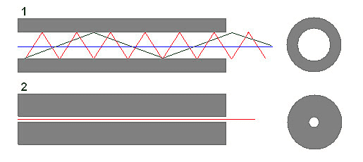
Diagram 1: a multimode fiber shown as a grey cladding with a blue axial ray and black and red zigzag ray paths reflecting inside; beside it a circular end view. Diagram 2: a single-mode fiber with a thin core line and a circular end view with a small central core.

Like here 1st picture contains multiple information.
I know also from physics that when the light beam crosses with each other then they sum up with each other and can get stronger or weaker like here :
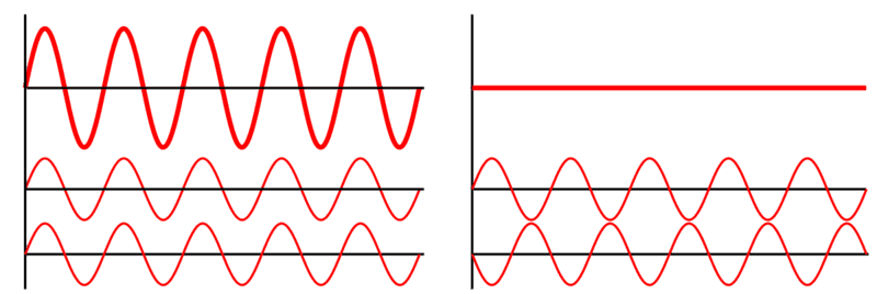
Two side-by-side diagrams of sine waves: left, a thick red wave above two thinner red waves, each beside a horizontal axis; right, a flat red line above two thinner red waves that are out of phase, showing constructive and destructive superposition.

Or here :

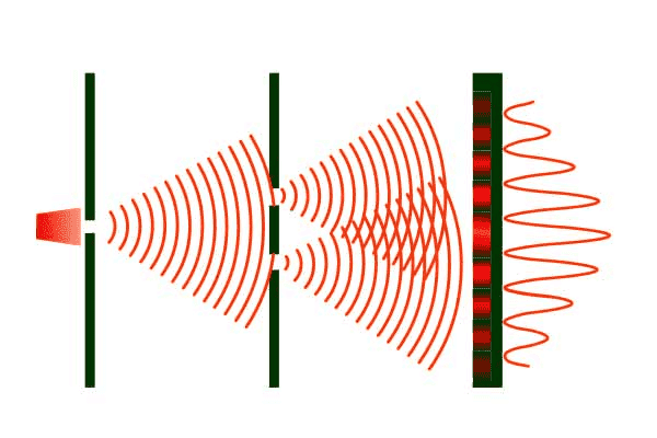
Double-slit interference diagram: a red light source on the left sends circular wavefronts through two slits, which then overlap to form a pattern of bright and dark bands on a screen at right, with an intensity curve beside it.

Doesn't the light in multimode also cross with each other like here ? And if so doesn't it change the information it contains ?

PS.
I'm really weak when it comes to physics that's why I'm trying to learn it a bit. Can someone explain it from the 3rd picture why is it weaker at the edges ?
I know that lasers have the same phase for each direction so when 2 same phases cross with each other doesn't it always increas the amplitude because they are in the same phase like in picture nr.2.

Like here :
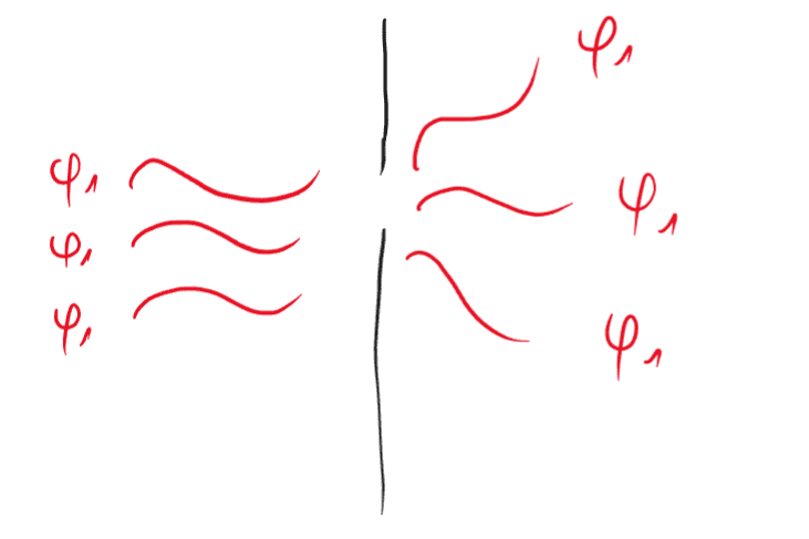
Hand-drawn diagram of a single slit: three incoming wavefronts labelled phi 1 on the left strike a black barrier, and the transmitted waves on the right are labelled phi 1, with the edge waves bending outward.

Laser and it spreads into different directions but because it is a laser it has the same phase not like in light bulb in which light has different phases.
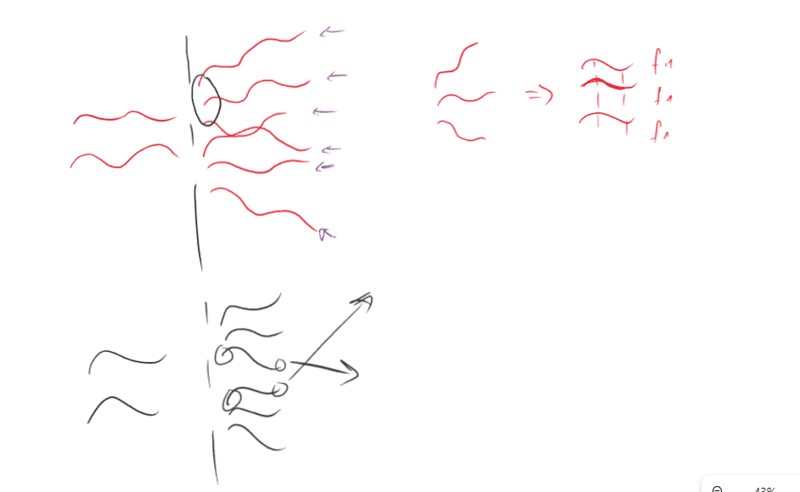
Hand-drawn diagram: red wavy rays enter a multimode fiber core from the left and reflect at angles, with arrows pointing back; beside it, three wave traces labelled f1, f2 and f3 are summed with an arrow.

Adding another laser will make now 2 light that have the same phase crossing each other. Will it increase the amplitude or decrease like in picture nr.2 ? They have the same phase but different direction so ?

Thank you and sorry for asking many questions.

EDIT :
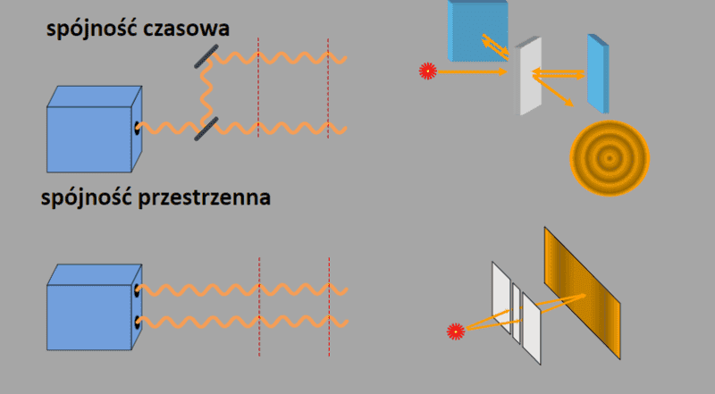
Diagram comparing temporal coherence (top, labeled spójność czasowa) and spatial coherence (bottom, labeled spójność przestrzenna) of light from a source, with wavy beams and red dashed lines marking reference points.

Sorry it's in polish. But here it is shown that two lasers have the same phase, they are not shifted.
 
Last edited:
Physics news on Phys.org
You seem to be over thinking this. A multimode fibre carries just one data stream. It is bigger than monomode, which makes interfacing easier and allows LED sources to be used. However, as the light can follow several paths through the fibre, a pulse arriving at the output is slightly smeared. This reduces the maximum signalling speed compared to single mode fibre, where no smearing occurs. The optical devices for multimode fibre are easier and cheaper but the maximum signalling speed is less.
 
  • Like
Likes   Reactions: nasu, hutchphd and berkeman
tech99 said:
You seem to be over thinking this. A multimode fibre carries just one data stream. It is bigger than monomode, which makes interfacing easier and allows LED sources to be used. However, as the light can follow several paths through the fibre, a pulse arriving at the output is slightly smeared. This reduces the maximum signalling speed compared to single mode fibre, where no smearing occurs. The optical devices for multimode fibre are easier and cheaper but the maximum signalling speed is less.
Maybe I am overthinking here a bit.
I just read that multimode carries more than 1 stream of light ? In monomode there is one light stream in the multimode there is much more than one. I had just a problem when it comes with these light "crossing" with each other, or how does the electronic device know which light contains what information. Something like that.
 
Xenon02 said:
I just read that multimode carries more than 1 stream of light ? In monomode there is one light stream in the multimode there is much more than one.
Can you please always post a link to whatever you "read"? That helps us to respond to your questions. Thank you. And more accurately, there are multiple "paths" that light can take in a multi-mode optical fiber, hence the spreading out of the received optical pulses that @tech99 mantioned. You can still use different wavelengths of optical light to carry different signal streams, but each will be limited in the maximum modulation frequency based on the spreading of that modulation due to the multi-path issue of the bigger fiber diameter.

Xenon02 said:
I had just a problem when it comes with these light "crossing" with each other, or how does the electronic device know which light contains what information.
Please don't anthropomorphize electronic devices. They hate it when you do that. :smile:

But seriously, as already stated, the different path lengths for the different modes in multi-mode FO just spreads out the receive modulation and limits how fast that modulation can be.

Can you also post links to the reading you've been doing about communcation modulation techniques and bandwidth limitations for each? Thanks.
 
berkeman said:
Can you please always post a link to whatever you "read"? That helps us to respond to your questions. Thank you.
Most of them are my university lectures.
Also I don't know if my polish PDF-s/websites will be understandable :D
Here is an example for multimode fibre site I've used : https://fiberm.pl/pl/blog/przeglad-swiatlowodow-jednomodowych-i-wielomodowych/b2

https://www.dipol.com.pl/swiatlowod_jednomodowy_i_wielomodowy_-_wprowadzenie_bib321.htm
It is as I read stated that multimode contains many stream light with the same wavelength
And it was very interesting for me because I've seen while having lecture that many light can be "added" into one fiber optic line, like 10 stream light added into one optic fiber.

So I was a bit confused.
Because like here :
Xenon02 said:
Two side-by-side diagrams of sinusoidal waves: left shows a thick red wave with two thinner red waves of equal frequency beneath it, right shows a flat line above two thin red waves in phase, illustrating wave superposition.

Or here :

Diagram of double-slit interference: a red wave source passes through two slits in the first barrier, spreading circular wavefronts that overlap and produce an intensity pattern of bright and dark fringes on the screen at right, plotted as a wave graph.

I knew that something happens to the light when they "meet" each other.
Also while I was writting about it I got again confused because why it is stronger at some point and weaker at other point because laser has the same phase like here :
Xenon02 said:
Hand-drawn diagram: left, several red wavy rays enter a fiber core boundary at different angles; right, three wave traces labelled f1, f2 and f3 combine with a arrow to a superposed waveform.

Adding another laser will make now 2 light that have the same phase crossing each other. Will it increase the amplitude or decrease like in picture nr.2 ? They have the same phase but different direction so ?

Thank you and sorry for asking many questions.

EDIT :

Diagram comparing temporal coherence (top, with a delayed wave split by mirrors and a ring interference pattern) and spatial coherence (bottom, with two waves from separated points and a double-slit style pattern).

As I can see they same the same phase.
Look at the second blue box it looks exactly like they are in phase so it should be increased but as some point it increases and at some it doesn't like here :
Xenon02 said:
Diagram of double-slit interference: a red wave source passes through two slits, spreading circular wavefronts that overlap to form bright and dark bands, with an intensity plot on the right.
berkeman said:
But seriously, as already stated, the different path lengths for the different modes in multi-mode FO just spreads out the receive modulation and limits how fast that modulation can be.

I don't really understand...
I mean what is wrong with my "theory" about what happens to the light when they meet each other like will they be stronger because of the interferation effect ? And if so wouldn't it change the information that the light was about to deliver ? Or somehow ? I don't know yet how light contains information but this is my blind quess.
I just get confused because there are many things that can happen to the light so it's confusing.
 
PS.
Here is also what I mentioned about connecting many source of light into one :
Diagram of a wavelength-multiplexing setup: eleven laser diode modules on the left feed fibre pigtails into a black multiplexer box, a single fibre coil links to a second box, and fibre leads fan out to eleven detector modules on the right.

It is from my university lectures. So there is only a photo.
I mean I get confused when it comes to this interferation effect, and if it changes anything here ...
Sorry for my confusion it is just that one physics law mixes my vision how everything works smoothly.
 
If you watch the sea waves bouncing off a harbour wall you will see that two waves can pass through each other without interference. As they travel over each other the peak amplitude is increased, but when they emerge the other side they come out unscathed.
In the picture, we see a fibre communication system using wavelength division multiplexing. Each source and each detector has a different wavelength. The waves co-exist in the fibre without interaction.
 
  • Like
Likes   Reactions: berkeman
@tech99
tech99 said:
If you watch the sea waves bouncing off a harbour wall you will see that two waves can pass through each other without interference. As they travel over each other the peak amplitude is increased, but when they emerge the other side they come out unscathed.

Why is that whey pass each other without interference ?
Doesn't it work like here ?

Diagram of double-slit interference: a red light source on the left sends waves through two slits in a barrier, spreading as overlapping circular wavefronts that create a pattern of bright and dark bands on a screen at right, with a sinusoidal intensity curve beside it.

Like they interfere with each other and at the end we see the new stronger wave at some point and weaker at the other point ?

tech99 said:
In the picture, we see a fibre communication system using wavelength division multiplexing. Each source and each detector has a different wavelength. The waves co-exist in the fibre without interaction.
Why the same wavelength can interfere but different wavelength can't ?
Also coming back to this quote. They co-exist in one optive fiber and doesn't interact ? Why ?
 
Xenon02 said:
I just read that multimode carries more than 1 stream of light ?
That's a really abysmal attempt to describe it; no wonder the OP was confused. In most fibres, other than the very thinnest, there are many different paths through the fibre, depending on the angle of entry from any single laser source (same original 'stream'). This would be multimode propagation. Getting most of the light power into the fibre is hard and the optics of launching will produce different delays over the different paths (imagine the 'fan' of rays entering the face of the fibre). The different delays will produce a number of 'pulses' at the other end, all at slightly different times, which blurs the transitions. (Inter-symbol interference) The spread of delays increases with fibre length so long fibres have a lower possible symbol rate. Also, bends in the fibre add to the effect.

A monomode fibre is thin enough to provide just one path and that is from just perpendicular incidence. The curve of a fibre has less and less effect as it is thinner and the single ray ('mode') propagates over a long distance. Of course, it's even harder to get a lot of power into a single mode and the optics is more demanding.
 
Xenon02 said:
@tech99Why is that whey pass each other without interference ?
Doesn't it work like here ?

View attachment 315190
Like they interfere with each other and at the end we see the new stronger wave at some point and weaker at the other point ?Why the same wavelength can interfere but different wavelength can't ?
Also coming back to this quote. They co-exist in one optive fiber and doesn't interact ? Why ?
I described the waves bouncing off a harbour wall. Where the waves overlap we can extract twice the energy if we wish. But if we do not extract any energy, the waves emerge again unaltered. With the multimode fibre, we launch several waves and they stay separate as they travel along the fibre, and we collect them at the end, giving us back our energy (minus fibre losses).
 
Xenon02 said:
Why the same wavelength can interfere but different wavelength can't ?
Also coming back to this quote. They co-exist in one optive fiber and doesn't interact ? Why ?
An interference pattern between light from two sources will only be seen if the path difference between the two path lengths is the same at all times in anyone place. So the maxes and mins will turn up in the same place all the time. A wide fibre could have bright and dark areas. If the light sources are not the same wavelength / frequency, the relative phases march past each other so there's never a max or min in the same place so there's no stationary pattern.
PS it's a different matter if the medium that the light passes through is not linear. Two beams can interact and produce new frequencies due to what they call intermodulation. Glass / air / water are linear for practical power levels of light.
 
If you were able to insert a probe into the multimode fibre, you would see interference effects happening. The two waves do not interact, the fields just add or subtract, giving local positions where the intensity is higher or lower. The addition of the two waves can never give you more energy out than energy in, it is just that in some positions the power density is increased.
 
  • Like
Likes   Reactions: sophiecentaur
Okey so correct me if you can @tech99 and @sophiecentaur
From this :
sophiecentaur said:
That's a really abysmal attempt to describe it; no wonder the OP was confused. In most fibres, other than the very thinnest, there are many different paths through the fibre, depending on the angle of entry from any single laser source (same original 'stream'). This would be multimode propagation. Getting most of the light power into the fibre is hard and the optics of launching will produce different delays over the different paths (imagine the 'fan' of rays entering the face of the fibre). The different delays will produce a number of 'pulses' at the other end, all at slightly different times, which blurs the transitions. (Inter-symbol interference) The spread of delays increases with fibre length so long fibres have a lower possible symbol rate. Also, bends in the fibre add to the effect.

A monomode fibre is thin enough to provide just one path and that is from just perpendicular incidence. The curve of a fibre has less and less effect as it is thinner and the single ray ('mode') propagates over a long distance. Of course, it's even harder to get a lot of power into a single mode and the optics is more demanding.

I understand I guess that multimodule gives more "paths" for single light in which this single light is bouncing from one side to another.
I don't understand the moment with the power light.
Also the delays does it mean that from one source of light we can get more ? And each one of them can have different delays ?
tech99 said:
I described the waves bouncing off a harbour wall. Where the waves overlap we can extract twice the energy if we wish. But if we do not extract any energy, the waves emerge again unaltered. With the multimode fibre, we launch several waves and they stay separate as they travel along the fibre, and we collect them at the end, giving us back our energy (minus fibre losses).

As I understand I don't know.
These light sources like in the picture from Post#1 picture one with multimodule.
Let's say we have 3 the same light, they "cross" each other and because they are the same they will intefere ? If yes then if we don't pick this moment then they will come back to normal and nothing changes ?
sophiecentaur said:
An interference pattern between light from two sources will only be seen if the path difference between the two path lengths is the same at all times in anyone place. So the maxes and mins will turn up in the same place all the time. A wide fibre could have bright and dark areas. If the light sources are not the same wavelength / frequency, the relative phases march past each other so there's never a max or min in the same place so there's no stationary pattern.
PS it's a different matter if the medium that the light passes through is not linear. Two beams can interact and produce new frequencies due to what they call intermodulation. Glass / air / water are linear for practical power levels of light.

But I don't understand why they have minimum when the requirement for the minimum is that 2 light wektors are in different phases, or more precisely shifted 180 degrees. But the laser has the same phase in every direction so it doesn't make sense for me. Doesn't these light can also meet when they are shifted not 180 degrees but 72 degrees ? Something happens then ?

Also Ps from quote 2.
Does it mean that the final effect from the post#1 picture 2 is that we receive the interference ? if we didn't receive the interference then I could receive normal light source without any increasing because of crossing 2 light sources ?

tech99 said:
If you were able to insert a probe into the multimode fibre, you would see interference effects happening. The two waves do not interact, the fields just add or subtract, giving local positions where the intensity is higher or lower. The addition of the two waves can never give you more energy out than energy in, it is just that in some positions the power density is increased.
I thought that the interference give the ability to connect two sources and increase the source ?

I'm sorry if what I said is stupid, I'm a hard learner. Some stuff just get's mixed in my mind :D
 
Xenon02 said:
Let's say we have 3 the same light, they "cross" each other and because they are the same they will intefere ? If yes then if we don't pick this moment then they will come back to normal and nothing changes ?
You need to start at the beginning of Interference / Diffraction in order to understand all this. This type of phenomenon is best described in terms of Waves and the most elementary situation is described in the Young's Slits effect. This is described in a Kahn Academy link. You may need to wait a while before connecting this with your original optical fibre question but it's the basis of everything optical. Early on in the video he uses 'rays' and shows that it doesn't work that way - a useful lesson!

PS Sorry for using the word "abysmal" if, in fact it was you who introduced the term "streams of light". I was assuming you got it from an uninformed source that shouldn't be trying to teach anything about light.
 
sophiecentaur said:
You need to start at the beginning of Interference / Diffraction in order to understand all this. This type of phenomenon is best described in terms of Waves and the most elementary situation is described in the Young's Slits effect. This is described in a Kahn Academy link. You may need to wait a while before connecting this with your original optical fibre question but it's the basis of everything optical. Early on in the video he uses 'rays' and shows that it doesn't work that way - a useful lesson!

PS Sorry for using the word "abysmal" if, in fact it was you who introduced the term "streams of light". I was assuming you got it from an uninformed source that shouldn't be trying to teach anything about light.
I've watched it, some of the things he had mentioned was very interesting like this :
Hand-drawn diagram of several green curved ray-like paths bouncing down to a wavy green sinusoidal line at the bottom, with one red dashed curve, and a double-headed arrow near the top.


I've added one element (in red lines) this isn't the peak as I know right ?
So what if a peak lines up over a not peak then something can happen ?

Also as I can understand from this picture is that it is the representation of the laser ray ?
So if I had laser rays in the fibre optic it would look like that ?
Handwritten sketch titled "Multifibre" showing two horizontal bars representing fibre boundaries, with a red zigzag wave and a blue zigzag wave crossing between them and meeting at a point near the middle.

And in scope it would look like that ? :
Hand-drawn diagram of two horizontal parallel bars with red and blue wave arcs travelling between them, the red and blue waves crossing and overlapping in the middle.

Now I wonder because they have different wavelength then they do not interfere, but if they had the same wavelength then they interfere in the middle and then nothing happens after that ?
Because here :
Simulation of circular green wavefronts spreading from the left, with white dots at intersection points and a white intensity curve with peaks on the right side.

This effect of lining up of the wavelength will result in the end like in the picture.
 
Last edited:
Xenon02 said:
So what if a peak lines up over a not peak then something can happen ?

Xenon02 said:
Simulation of two-source circular wave interference: green concentric arcs with white dots at constructive points, brown dots at cancellation points, and a white intensity curve with bumps along the right edge.
Green lines represent peaks of value +1 and half way between them are values of -1 (troughs)
The white dots are places where the peaks (+1 and +1) coincide and the result is twice the amplitude(+2) of one. Where two troughs coincide, the value is -2. The fringes (white bumps) represent high energy arriving over each cycle and are at the end of the lines of white dots and (not drawn) troughs.
At your brown 'dot', there is a peak (+1) and a trough (-1), adding together to produce an amplitude of zero. Zero energy flows in this direction.
Other combinations will produce +1+0 = +1 in other directions.
 
sophiecentaur said:
Green lines represent peaks of value +1 and half way between them are values of -1 (troughs)
The white dots are places where the peaks (+1 and +1) coincide and the result is twice the amplitude(+2) of one. Where two troughs coincide, the value is -2. The fringes (white bumps) represent high energy arriving over each cycle and are at the end of the lines of white dots and (not drawn) troughs.
At your brown 'dot', there is a peak (+1) and a trough (-1), adding together to produce an amplitude of zero. Zero energy flows in this direction.
Other combinations will produce +1+0 = +1 in other directions.

What I meant is that the wave is a sinusoidal so the peaks are at certain points but those waves have also spots where there is no peak like here :
Hand-drawn green sketch of several curved ray paths bouncing down through a fiber, with dashed red lines marking an intermediate position, ending in a wavy sinusoidal curve along the bottom.

I've used the red color to show it. It is not the peak it is something between the peaks.
And I was wondering what happens if not a peak lines up with peak.
Why at the end some peaks are stronger than the other peaks ? The center peak is stronger than the side peaks. Does the energy overlap ? Because before it was said that those increases doesn't stack, like it increases but when it exits this spot then it comes to normal here I see that they stack up.

A and what do you think of my interpretation of light rays in fibre optic multimode?
 
@sophiecentaur I don't know if I conveyed exactly what is my problem but I slowly am getting how things works.
I just don't get what happens if we have not the peak of waves but something in between ? Like peak wave lines up with not peak. Or why peak of the wave lines up with the valley peak of the other wave even though they are in phase. Also why the light gets weaker do they stack up ? I read that interference doesn't stack up it just interfere and when they exit this point then they are normal without any increases or decreases.
 
Xenon02 said:
Like peak wave lines up with not peak.
For every peak (call it +1) there is an opposite trough (-1) these values are either side of an average value of zero. As the wave is sinusoidal, there is a continuum of values between peaks and troughs. "not peak" is not a meaningful term because it can refer to anywhere that's not an actual positive peak.
Read the descriptions more carefully and try not to let your own model of what's going on interfere with grasping the accepted model.
At the 'projection screen' waves are arriving everywhere. At the peaks of the pattern, the variation is between +2 and -2. elsewhere, the variation can be between +0.4 and -0.4 or +0.00012 and -0,00012 or any other values. At perfect cancellation, you get no variation about zero.

Personally, I find demonstrations of surface water waves very difficult to make sense of because the propagating waves get messed up by other standing waves that always seem to show up and also, flickering lighting upsets things too. I'd say that interfering light waves, accompanied by well drawn diagrams are the best way in. Yes - it's abstract stuff but so is a lot of Physics.
 
sophiecentaur said:
For every peak (call it +1) there is an opposite trough (-1) these values are either side of an average value of zero. As the wave is sinusoidal, there is a continuum of values between peaks and troughs. "not peak" is not a meaningful term because it can refer to anywhere that's not an actual positive peak.
Read the descriptions more carefully and try not to let your own model of what's going on interfere with grasping the accepted model.
At the 'projection screen' waves are arriving everywhere. At the peaks of the pattern, the variation is between +2 and -2. elsewhere, the variation can be between +0.4 and -0.4 or +0.00012 and -0,00012 or any other values. At perfect cancellation, you get no variation about zero.

Personally, I find demonstrations of surface water waves very difficult to make sense of because the propagating waves get messed up by other standing waves that always seem to show up and also, flickering lighting upsets things too. I'd say that interfering light waves, accompanied by well drawn diagrams are the best way in. Yes - it's abstract stuff but so is a lot of Physics.
@sophiecentaur
So let me use paint as a my understanding point :

Three stacked red sine waves of different wavelengths or phases, with green and blue markers on their crests and troughs; a green plus sign and blue plus sign mark points on the middle and bottom waves.

in this picture there is an interference.
On the screen I can have +2 colored by green dots or I can have less but still increased colored by blue let's say it is +1 or 0.
So at the end of this interference from this video you have send me :

Screenshot of a wave simulation showing green circular wavefronts spreading from the left, with white dots marking points of constructive interference and a white intensity curve with peaks plotted on a vertical line at the right; label reads 540 energy points.


This big increase is exactly the green dots I have shown in the picture before ?
And also increase but smaller on the side are like my blue dots like in the picture before ?
Also what did I mean by not peak lining up with peak amplitude, something like this :

Two red sine waves drawn one above the other, the lower wave shifted horizontally relative to the upper one so their peaks do not line up.

Not in phase because here :

Diagram of two sinusoidal waves drawn in dark red, one above the other, with a horizontal red line above them; the waves cross at regular points, showing them out of phase.

But it works ?
Also the author of the video said that the waves are in phase but here it doesn't look like that.
 
Xenon02 said:
Also the author of the video said that the waves are in phase but here it doesn't look like that.
They are clearly in anti phase there (in the direction of the gold points) - resulting in a zero sum. I can't be bothered to find this in the video but did he really say that? Of course they are always in a constant phase relationship at any point on the screen so the result will be a sine wave - just with different magnitude.
Have you taken on board the importance of the + and- signs in the combining of the waves?
 
sophiecentaur said:
Have you taken on board the importance of the + and- signs in the combining of the waves?
@sophiecentaur
Yes I have I guess understood the impotance of + and - sings. But I didn't understand why is it shifted in phase even though they are in phase so they should be increasing ?
I mean here is also shifted in phase waves :

Two red sine waves drawn one above the other, the lower wave shifted in phase relative to the upper wave, both with the same wavelength and amplitude.

Because those waves can meet each other like that if they can meet if it's shifted 180 degrees.
I just don't understand the logic of why it is shifted. And why on the screen only the middle one is the strongest and further they are weaker.
Because tech and you mentioned that they interfere but when they exit they are again normal :
tech99 said:
The two waves do not interact, the fields just add or subtract, giving local positions where the intensity is higher or lower. The addition of the two waves can never give you more energy out than energy in, it is just that in some positions the power density is increased.
tech99 said:
I described the waves bouncing off a harbour wall. Where the waves overlap we can extract twice the energy if we wish. But if we do not extract any energy, the waves emerge again unaltered.
I don't get it ...
On the video the middle one is stronger the other are not.
the phases they are in phase but they can cross each other when they are shifted in 180 degrees.
but what if they cross like that :

Two sine waves drawn in dark red, one above the other: the upper wave has its peaks and troughs slightly offset from the lower wave, so the two are out of phase.

They can meet like that right ? Even if the rays are in phase in every direction like you mentioned.

Sorry I get confused ...
 
Xenon02 said:
I just don't understand the logic of why it is shifted.
It's the difference in path length that causes different phase difference as you look along the screen. It's a very sensitive test of length and it is used for Interferometry to measure tiny movements.
 
  • Like
Likes   Reactions: vanhees71
@sophiecentaur
sophiecentaur said:
It's the difference in path length that causes different phase difference as you look along the screen. It's a very sensitive test of length and it is used for Interferometry to measure tiny movements.
I don't really understand it is it possible to give a sketch of how it looks like ? Difference in the path doesn't tell me a lot, but okey let's say there is this difference in the path.
Usually when there is interference then +1 peak lines up with +1 peak or +1 peak lines up with -1 peak.
But what if it's in between like here :

Two sine waves drawn in dark red, one above the other, with the lower wave slightly out of phase with the upper one, both showing about five cycles.

Also I asked there why on the screen there is only one very bright point and the other bright points are weaker than the middle one.

Simulation of green concentric circular wavefronts from two point sources, with white dots marking bright interference points and a white intensity curve plotted vertically on the right; label reads 540 energy points.


Like here.
Beause it looks like the interference are stacking up ? Like +1 lines up with +1 then it's +2 then +2 lines up with +1 and it's +3 ?
I thought of it like that but it was mentioned that the wave when it exits the interference it comes back to normal like here quotes :

tech99 said:
The two waves do not interact, the fields just add or subtract, giving local positions where the intensity is higher or lower. The addition of the two waves can never give you more energy out than energy in, it is just that in some positions the power density is increased.

tech99 said:
I described the waves bouncing off a harbour wall. Where the waves overlap we can extract twice the energy if we wish. But if we do not extract any energy, the waves emerge again unaltered.
 
Xenon02 said:
Also I asked there why on the screen there is only one very bright point and the other bright points are weaker than the middle one.
Let's get this out of the way first: the peaks are not all the same height because the slits do not produce an omnidirectional pattern. It's a practical problem, due to diffraction. Light off to one side is less intense because the slits are not infinitely thin. You must wait to understand about this and it's not relevant to the basic process.
Xenon02 said:
Usually when there is interference then +1 peak lines up with +1 peak or +1 peak lines up with -1 peak.
But what if it's in between like here :
It's ALL interference. Sometimes it's constructive (maxes), sometimes it's destructive (in a null) and the rest of the time, when the two wave amplitudes are unequal, you can get a value in between.

I have a feeling that you are trying to learn this by the very dodgy 'Question and Answer' method. Every time you get to something difficult you ask a question instead of accepting what's said and trying to figure it out from that. You cannot rely on being able to spot what you really need to know. Do not skip over the steps in the Khan Academy tutorial . Don't expect it to be easy or to make instant sense.
The shame is that, if you were prepared to do a bit of Maths here, it would all be much simpler.
 
  • Like
Likes   Reactions: DaveE
Where does the path difference come from?? Those concentric circles show equal steps in time delay. Look at the distance from one slit and the other; equal from each slot at points that are along the central line, it's always a different distance from each slot. If the difference is a whole number of wavelengths then you get constructive interference.

Distance from the slot corresponds to total phase delay.
 
sophiecentaur said:
Let's get this out of the way first: the peaks are not all the same height because the slits do not produce an omnidirectional pattern. It's a practical problem, due to diffraction. Light off to one side is less intense because the slits are not infinitely thin. You must wait to understand about this and it's not relevant to the basic process.
@sophiecentaur
I thought of the intensity of this bright points in the screen as an essential so I was asking.
sophiecentaur said:
It's ALL interference. Sometimes it's constructive (maxes), sometimes it's destructive (in a null) and the rest of the time, when the two wave amplitudes are unequal, you can get a value in between.

I have a feeling that you are trying to learn this by the very dodgy 'Question and Answer' method. Every time you get to something difficult you ask a question instead of accepting what's said and trying to figure it out from that. You cannot rely on being able to spot what you really need to know. Do not skip over the steps in the Khan Academy tutorial . Don't expect it to be easy or to make instant sense.
The shame is that, if you were prepared to do a bit of Maths here, it would all be much simpler.

I'm sorry I usually find something that isn't covered in the basics so it's confusing for me.
Because when there are 2 different wave lenghts then I thought that they don't interfere but from this quote I guess they can ?
sophiecentaur said:
Where does the path difference come from?? Those concentric circles show equal steps in time delay. Look at the distance from one slit and the other; equal from each slot at points that are along the central line, it's always a different distance from each slot. If the difference is a whole number of wavelengths then you get constructive interference.

Distance from the slot corresponds to total phase delay.

distance from one slit and the other you mean a single source or the slits from the connecting both sources ?
sophiecentaur said:
equal from each slot at points that are along the central line, it's always a different distance from each slot. If the difference is a whole number of wavelengths then you get constructive interference.
I don't understand this part.PS.
sophiecentaur said:
I have a feeling that you are trying to learn this by the very dodgy 'Question and Answer' method. Every time you get to something difficult you ask a question instead of accepting what's said and trying to figure it out from that.

I know this might be weird way. But I don't know how to understand it in different way, I always find something that doesn't make sense for me. Sorry of course.
I want to learn just how the light works but when I see new stuff it just bothers me why something doesn't happen when I put like 2 light rays in the multimode or something. I'm also trying to learn how lasers work and how optic amplifier works (because they seem similar, but in optic amplifier we don't want to have laser effect I don't know to be honest why but I'm still learning).
 
Just hang on a minute. What “two wavelengths” are you introducing? The wavelengths from each slit are the same as they come (split) from the same source.

You have zero chance with this if you don’t clear up the basics. I’m getting bored with your reactions.
 
  • Like
Likes   Reactions: DaveE and berkeman
sophiecentaur said:
Just hang on a minute. What “two wavelengths” are you introducing? The wavelengths from each slit are the same as they come (split) from the same source.
I said introduced it saying also about the multimode fibre :
Xenon02 said:
I'm sorry I usually find something that isn't covered in the basics so it's confusing for me.
Because when there are 2 different wave lenghts then I thought that they don't interfere but from this quote I guess they can ?
sophiecentaur said:
You have zero chance with this if you don’t clear up the basics. I’m getting bored with your reactions.
I just wonder what I'm doing wrong then.
All I really know is that there is one source that is for example a laser. In the video of splits into two sources that are the same. Same phase same wavelength. They interfere with each other. Peaks lines up with peaks and that increases the amplitude or decreases the amplitude.
Shifts are cause of the direction the wave is directed to I guess.
Also this situation can also happen in two same sources :

Two red sine waves drawn one above the other, with the lower wave shifted horizontally relative to the upper one, showing a phase offset between them.