Homework Help Overview
The discussion revolves around the behavior of diodes, specifically addressing the forward voltage drop, often noted as ##V_{ON}##, which is typically around 0.7V for silicon diodes. Participants are examining a graph related to half-wave rectification and questioning the representation of voltage in the context of diode operation.
Discussion Character
- Exploratory, Conceptual clarification, Assumption checking
Approaches and Questions Raised
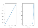
- Participants are attempting to clarify the meaning of ##V_{ON}## and its implications in diode behavior. Questions arise regarding the specifics of the graph, including what the y-axis represents and whether the graph is accurately depicting the voltage across a resistor or the diode output. There are discussions about the characteristics of ideal versus real diodes and the implications of forward voltage on current flow.
Discussion Status
The conversation is ongoing, with participants providing insights and raising questions about the clarity of the graph and the definitions involved. Some participants suggest that the graph lacks necessary details, while others are exploring the implications of diode behavior in different contexts. There is no explicit consensus, but several lines of reasoning are being explored.
Contextual Notes
There are indications that the original question may be based on assumptions about the type of diode being discussed, and the representation of voltage in the graph is under scrutiny. Participants are also noting the potential ambiguity in the educational materials being referenced.