Electric field vs coupling between transmission lines

Click For Summary

Discussion Overview

The discussion revolves around the relationship between electric fields and coupling in a system of three coupled transmission lines positioned above a ground plane. Participants explore the mathematical modeling of mutual capacitances and electric fields, particularly in the context of high-frequency AC signals.

Discussion Character

  • Exploratory
  • Technical explanation
  • Debate/contested
  • Mathematical reasoning

Main Points Raised

  • One participant seeks to derive an equation correlating mutual capacitances and electric fields between three coupled lines, noting that the electric field around the middle line becomes more concentrated as the distance between lines decreases.
  • Another participant questions whether the analysis is limited to DC static electric fields and emphasizes the importance of polarity modes in systems with more than two conductors.
  • Some participants clarify that they are considering high-frequency AC signals and discuss the implications of coupling dominated by magnetic interactions.
  • One participant suggests that the reduction of distance between lines increases mutual electric fields, potentially leading to a decrease in the electric field of the middle line to the ground plane.
  • Another participant points out that to change voltage across capacitance, a current must flow, generating a magnetic field, and notes the role of the ground plane as a mirror image in the system.
  • There is a discussion about modeling the structure using self-capacitances and mutual capacitances, with some participants advocating for the inclusion of mutual and self-inductance in the model.
  • One participant inquires about the appropriate starting point for deriving relationships between coupling, mutual capacitance, and electric fields, mentioning various mathematical approaches like Laplace's equation and telegrapher's equation.
  • Another participant suggests defining the structure as a two-port network, emphasizing the necessity of considering inductive magnetic coupling alongside capacitive electric coupling.
  • There is a proposal to analyze the electric field distribution by treating the ground plane as a zero equipotential and establishing boundary conditions for numerical solutions.

Areas of Agreement / Disagreement

Participants express multiple competing views on the modeling approach and the factors influencing electric field distribution and coupling in the system. The discussion remains unresolved, with no consensus on the best method to derive the desired relationships.

Contextual Notes

Participants highlight limitations in their assumptions, such as the treatment of the ground plane and the need for boundary conditions in numerical solutions. There is also a lack of clarity on the dielectric properties of the medium between the ground plane and the lines.

Young_Scientist23
Messages
11
Reaction score
0
TL;DR
Derivation of equation which correlate electric fields of coupled lines with coupling. The question is: what will happen with electric field between line and ground plane in scenario, where coupling is strong.
Hello All,

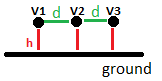
I'm trying to create equation which can describe relation between electric fields of three coupled-lines and coupling between them. Let we say that, we have thee lines having infinit length which are placed above ground plane in distance h. The distance between coupled lines is marked as [l]d[/l]. Each line has defined electric potential (e.g. line no. 1 has potential ##V_{1}## and so on). Now what I'm trying to do. I'm trying to create equation which can correlate mutual capacitances (##C_{12}##, ##C_{23}##) between the lines, with their electric fields (existing between the lines and ground plane - ##\vec{E_{1}}\\##, ##\vec{E_{2}}##, ##\vec{E_{3}}##). It is quite intuitive that, when you decrease distance between the lines, the electric field around middle line no. 2 will be more "concentrated" between the lines nor the ground plane. Moreover, I'm observing it in some simulations and capacitance matrices. I'm just wondering how to proof that mathematically.
I take Laplace to start solving this case, however I'm not quite sure whether it is good way to solve the issue. For this case I derive folowing equations:

$$\frac{d^2V_{1}(x)}{dx^2} - C_{12}\frac{d^2V_{2}(x)}{dx^2} = 0$$, $$\frac{d^2V_{2}(x)}{dx^2} - C_{12}\frac{d^2V_{1}(x)}{dx^2} - C_{23}\frac{d^2V_{3}(x)}{dx^2} = 0$$, $$\frac{d^2V_{3}(x)}{dx^2} - C_{23}\frac{d^2V_{2}(x)}{dx^2} = 0$$.
When I'm trying to solve the second equation in terms of distribution of electric fields and mutual capacitances, I'm "landing" in this equation:
$$\vec{E_{2}} = (\vec{E_{1}} + \vec{E_{3}})C_{mut} $$

where ##C_{mut} = C_{12} = C_{23}##.

Assuming that the electric fields of lines no. 1 and no. 3 are constant, the electric field ##\vec{E_{2}}## of line no. 2 decrease only, when distance between lines is increasing, what has no sense. What I'm doing wrong ? Could someone come up with the correct thought ?
Best Regards,

Tom
 
Physics news on Phys.org
Are you only considering DC, static electric fields ?
If so, for more than two conductors, the polarity "mode" will be important.
I think we need a diagram of the physical arrangement you are considering.

Within AC transmission lines, coupling is dominated by the magnetic interaction between the line currents.
 
I'm considering AC in really high frequencies. I'm sending some figure in attachment. I'm trying to describe coupling between lines by using mutual capacitances between the lines.
 

Attachments

  • Figure.png
    Figure.png
    1.3 KB · Views: 163
Young_Scientist23 said:
I'm considering AC in really high frequencies.
With d and h << λ;
Are you studying the cross-talk between quite independent signals, or is this a three-phase supply, in which case the phase of the signals is important?
 
With d and h << λ;
Yes.

Well, actually I'm not focusing on this case in terms of signal integrity,signal processing. Let we say that, I'm supplying obły the middle line (the "outside " lines - 1 and 3 are not polarized). My intuition and simulations are telling me that, the reduction of distance will change distribution of electric field in this structure. The closer will be the lines, the stronger coupling between them and smaller will be electric field of line 2 to the ground plane. I also assuming that, widths of lines 1 and 3 are greather than line 2. Therefore, electric fields of those lines (to the ground plane) will be quite large.
 
I prepared addition figure:
Fig_2.png

On the left we have case in which all coupled lines are in some relativelly large distance to each other. The electric field $$E_{2}$$ is existing in this case. However, if you decrease distance between the lines, the mutual electric fields are increasing what leads to decreasing of the field E2 which can be even equal to zero. My intuition is seying that this has sense, because concentration of electric fields between the lines can compensate field od middle line (E2). However, I don't know how to describe this fact with math.

Regards,
 
In order to change the voltage on the capacitance between conductors, a current must flow, that will generate a magnetic field. What you are describing as an AC field on a capacitor, is actually a transmission line.

The conductive ground-plane will form a mirror. The structure above the ground will appear as an image, below the ground. The ground disappears, to become a plane of symmetry.

You have not specified a supporting dielectric between the ground plane and the tracks.
 
You are right that, those lines can be treated as transmission lines. However, according to the theory, such a structures can be modeled by its self-capacitances (capacitances between conductors and ground plane), coupled by mutual capacitances. For calculations we can assume dielectric permitivity equal to 1.
 
Young_Scientist23 said:
However, according to the theory, such a structures can be modeled by its self-capacitances (capacitances between conductors and ground plane), coupled by mutual capacitances.
Yet at the same time, it must be modelled as having mutual and self inductance that support travelling waves on the structure.
 
  • #10
Ok, but how to derive relation between coupling/mutual capacitance/electric field between the lines and self-capacitance/electric field between middle line and ground plane ? How to start with it ? What I have to use ? Laplace, telegrapher's equation....????
 
  • #11
Young_Scientist23 said:
How to start with it ?
Define the structure as a two port network. Then model the network between the ports. The capacitive electric coupling cannot be modelled without the inductive magnetic coupling.
The impedance of the ports, and the time delay through the network, are related to, the inductance per unit length, and the capacitance per unit length.
 
  • #12
I've to model it as a two port network, even if I'm feeding only one port ? I'm just wondering how to solve this problem (how to calculate electric fields distribution) by using some method from EM field theory.
 
  • #13
As it is a transmission line, it must have two ports. It can be terminated at the second port with its characteristic impedance, to prevent reflections. That makes it a one port impedance.

To map the electric field within the line, look at the cross-section and make the ground plane a zero equipotential. Assume DC, say 100 volt, on the central line. What is the voltage on the outer two lines?

You can then solve analytically for the static electric field.
Where it is open to infinity, you must establish boundary conditions before solving it numerically by relaxation or the exodus method.
 

Similar threads

  • · Replies 4 ·
Replies
4
Views
3K
  • · Replies 2 ·
Replies
2
Views
2K
  • · Replies 8 ·
Replies
8
Views
2K
  • · Replies 1 ·
Replies
1
Views
5K
  • · Replies 1 ·
Replies
1
Views
2K
  • · Replies 25 ·
Replies
25
Views
3K
  • · Replies 1 ·
Replies
1
Views
693
  • · Replies 43 ·
2
Replies
43
Views
5K
  • · Replies 1 ·
Replies
1
Views
2K
  • · Replies 4 ·
Replies
4
Views
1K