Fan-motor system resonance problem

40 replies · 9K views · last reply
ArnoVonck said:
Yes the impeller has been replaced with a completely new one. Both have been balanced, statically and dynamically.
.....
There is most certainly some deposits on the vanes. But the problem was already there before the build-up of these.

Dynamic balancing is the key in this case, but it should be done as an assembly (all the rotating masses), including shaft and key.
If not possible, testing the dynamic balance of the shaft alone could eliminate the possibility of a bent shaft (which I suspect).

Besides any fluid pulsing cause (if any), the resonance problem must have its root in masses that rotate out of balance, even if in a very small magnitude.
If that lack of balance can't be located and measured and corrected, modifying things to increase the natural frequency of the vibrating system is the next step.
Evidently, those added angles did not do much for that.

What is the meaning of your following statement?
I'm kind of rethinking the weights on the impeller to balance it out though.
... it's not that easy to show pictures of bearings and couplings since the place has to go in shutdown to turn the fan off. (It runs on 30 Hz now)
No problem, just trying to understand the arrangement of motor, coupling, shaft, air seal (if any) and bearings.
If not possible, pictures from different angles around the fan could help us.

It seems to be a cantilever impeller arrangement, which can make vibrations worse.
One of your pictures seem to show a solid bridge by-passing the isolation of duct-fan provided by the canvas connection.

Any luck with a video via YouTube?
 
Lnewqban said:
Any luck with a video via YouTube?
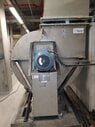
I shared some links to these video's in a reply above
ArnoVonck said:
Video 1:
Video 2:
Here they are
 
Lnewqban said:
What is the meaning of your following statement?
The fan has been balanced out by adding some weights to the impellers. This has been done when I wasn't on internship here yet. When I looked at the fan spinning without media through it, it seemed these weights were actually Off-balancing the impeller. I'm thinking about taking the weights off and then seeing how the system does when rotating.
 
Be sure to mark which weight goes where. That will save you a LOT of time if things get worse without them! :eek:

Also was the original balancing a static balance or a dynamic balance in 3 dimensions?
i.e. the usual out-of-round or off-center mounting problem
versus
also balancing for wobble parallel to the spin axis. (important for centrifugal fans)
 
  • Like
Likes   Reactions: ArnoVonck, berkeman and Lnewqban
Lnewqban said:
No problem, just trying to understand the arrangement of motor, coupling, shaft, air seal (if any) and bearings.
If not possible, pictures from different angles around the fan could help us.
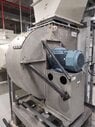
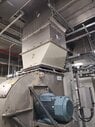
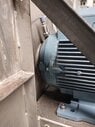
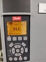
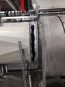
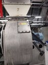
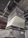
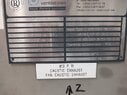
I'm sorry for the late answer. I've been on a holiday. I've went and took some pictures of the entire unit to maybe get you a better idea.
 
Attachments
  • Large stainless steel centrifugal fan housing on a steel frame, with a blue electric motor mounted on its side and diagonal steel braces supporting the motor.
    WhatsApp Image 2023-04-18 at 10.17.32 (1).jpeg
    46.3 KB · Views: 172
  • Industrial centrifugal fan with a grey sheet-metal housing and a large blue electric motor mounted beneath it, with a tapered white duct section and ductwork running overhead in a plant building.
    WhatsApp Image 2023-04-18 at 10.17.32 (2).jpeg
    48.8 KB · Views: 177
  • Photo of a grey industrial electric motor with finned housing mounted on a steel base plate beside a metal enclosure wall, with a small pressure fitting visible at the top left.
    WhatsApp Image 2023-04-18 at 10.17.32 (3).jpeg
    38.5 KB · Views: 161
  • Industrial centrifugal fan unit on a steel base, with a blue electric motor mounted on a sheet-metal housing and a grey fan casing bearing a Rucon label.
    WhatsApp Image 2023-04-18 at 10.17.32.jpeg
    40.8 KB · Views: 168
  • Photo of a Danfoss variable frequency drive keypad with an amber LCD showing Status, 82.0%, 19.1A, 4.71kW, and 31.1 Hz, plus Auto Extern Op ref. text, with Status, Quick Menu, Main Menu, Alarm Log, navigation and control buttons below.
    WhatsApp Image 2023-04-18 at 10.17.33 (2).jpeg
    28.4 KB · Views: 175
  • Photo of an industrial fan installation: a white rectangular duct flange joins a large cylindrical grey metal fan housing, with a black flexible canvas connector bridging the two flanges and steel support framing below.
    WhatsApp Image 2023-04-18 at 10.17.33 (1).jpeg
    38.1 KB · Views: 177
  • Industrial centrifugal fan with a stainless steel casing on a steel base frame, driven by a blue electric motor mounted on top, with a cable tray and a control panel at right.
    WhatsApp Image 2023-04-18 at 10.17.33 (3).jpeg
    44.7 KB · Views: 178
  • Photo of an industrial centrifugal fan housing in stainless steel with a bolted access panel bearing a small red and yellow warning label, a blue electric motor mounted beside it, and a square duct flange above.
    WhatsApp Image 2023-04-18 at 10.17.33.jpeg
    42.6 KB · Views: 192
  • Photo of an industrial fan housing with a tapered white-grey duct section mounted on a larger grey base unit, with a Rucon label and a Calix label visible, under exposed ceiling pipes and cable trays.
    WhatsApp Image 2023-04-18 at 10.17.34 (1).jpeg
    42.6 KB · Views: 160
  • Stainless steel fan nameplate from Rucon ventilatoren, listing fan type, airflow of 20,000 m3/h, motor ABB M3AA 180 MLA 8 4P-18.5 kW, 3X 400/690V, speed 1476, max temp 60°C and total weight 770 kg, with a label reading 813 F 11 CAUSTIC EXHAUST FAN CAUSTIC EXHAUST below.
    WhatsApp Image 2023-04-18 at 10.17.34.jpeg
    60.1 KB · Views: 159
When you run it a rated design rpm (1470 rpm), are you getting rated static pressure?

Are there other systems tied into the duct? I assume it's going to a scrubber?
 
  • Like
Likes   Reactions: russ_watters and ArnoVonck
Based on Video #2 in Post #17, it appears that the blower housing has a mechanical vibration at 18.2 Hz. Mechanical vibrations are analyzed as spring - mass systems. The mass in this system is the blower housing, the spring is the side of the housing in the photos, and the motor base is fixed. That's why the request for the test in Post #27. Sometimes, your fingers are all the test equipment that you need. This might be one of those times, but you need to run the test to find out.

If so, the remedy is simple. Weld on a pair of stiffeners as shown by the heavy black lines in the image below.

Photo of an industrial centrifugal fan with a stainless steel scroll housing, an inlet hopper on top, and a blue electric motor mounted on a side bracket. Two black lines are drawn over the housing side.

You can leave the angled braces where they are, or make new ones that connect the same location on the base to the top of the stiffeners.

The theory is as follows: Natural frequency = ##\sqrt{\left( \frac K M \right)}##, where:
K = Stiffness
M = Mass
Since we want to increase natural frequency from 18 Hz to a value above the maximum operating speed of 30(?) Hz, it is necessary to increase the ratio of K to M by about a factor of 4. Reducing the vibrating mass that much is not practical, but it is practical to increase the stiffness. The stiffness of a thin plate is very low, and it is easy to increase that stiffness by a factor of several times by adding the stiffeners shown.
 
  • Like
Likes   Reactions: russ_watters, ArnoVonck and DaveE
A thought: Those diagonal stiffeners ? Do they resonate ?? If so, can you add masses to 'quench' them ??
 
jrmichler said:
That's why the request for the test in Post #27.
The 3rd of May we'll do another run-up test. I'll do as you said in Post #27
 
erobz said:
When you run it a rated design rpm (1470 rpm), are you getting rated static pressure?

Are there other systems tied into the duct? I assume it's going to a scrubber?
No we don't get rated static pressure. Indeed, it's going to a scrubber.
 
ArnoVonck said:
No we don't get rated static pressure. Indeed, it's going to a scrubber.
I'm assuming your s.p. was too high, which was why it is currently being run at 1086 rpm? Or is it the vibrations just passing through 1086 rpm on the way to 1470 rpm the issue?