iScience
- 466
- 5
This isn't a homework problem, but i embarrassingly keep getting stuck on this simple problem..
Suppose my turbine's blades are flat surfaced.
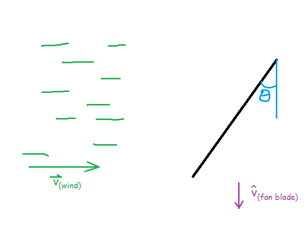
the green lines represent the wind towards the black turbine blade at the right. the blade is drawn as an edge view, such that you'd be looking towards the center motor.
i've tilted my blade at some angle theta in reference to the plane perpendicular to the direction of the wind (as depicted by the blue angle). finally, the purple arrow is just to represent the direction that the turbine's blade will end up moving towards.
consider the next image
(Assumptions being made:
* Elastic collision
* Smooth surface (such that no tangential component of force is transferred to the surface) )
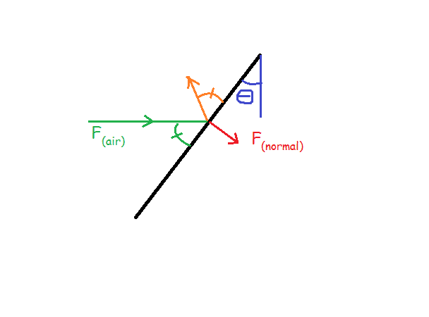
This is a force diagram as well as a path diagram just put into one.
Green & orange arrows: represent the incident and reflected path of a air particle (since no tangential force component transferred, angle of incidence (green angle) should equal angle of reflection (orange angle))
Red arrow:Transferred normal force component by collided particle.
$$F(norm)=F(air)cos\theta$$
now breaking the F(norm) into its components WRT the blade's motion...
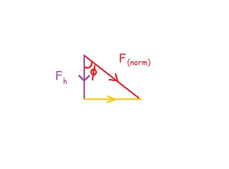
The purple vector F(horizontal), being the force comp. responsible for propelling the turbine blade.
to explicitly show what [itex]\phi[/itex] is:
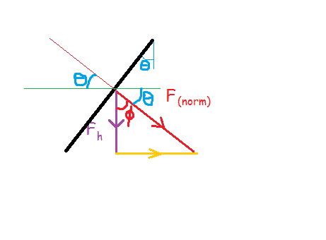
the blade's surface is superimposed on the previous image with all the angles drawn
so then [itex]\phi[/itex]= 90-[itex]\theta[/itex]
$$F_{h}=F_{norm}cos(90-\theta)=F_{norm}sin\theta=F(air)cos\theta sin\theta$$
but the flux must also be considered, since greater angle means less orthogonal surface area on blade surface.
Flux:
$$\Phi=\int F_{h}\cdot dA$$
since area is flat and surface dot product is constant..
$$\Phi=F_{h}Acos\theta=F(air)cos^{2}(\theta)sin(\theta)A$$
to find the maximum i just graphed the [itex]\theta[/itex] terms on my calculator, and here's what bothers me:
it gives me multiple peaks at intervals of 35.26° in both + & - directions. Moreover all the peaks are @ the same height.
peaks @:...
...
...
-144.74°
-35.26°
35.26°
144.74°
...
...
...What am i doing wrong?thanks guys
Suppose my turbine's blades are flat surfaced.
the green lines represent the wind towards the black turbine blade at the right. the blade is drawn as an edge view, such that you'd be looking towards the center motor.
i've tilted my blade at some angle theta in reference to the plane perpendicular to the direction of the wind (as depicted by the blue angle). finally, the purple arrow is just to represent the direction that the turbine's blade will end up moving towards.
consider the next image
(Assumptions being made:
* Elastic collision
* Smooth surface (such that no tangential component of force is transferred to the surface) )
This is a force diagram as well as a path diagram just put into one.
Green & orange arrows: represent the incident and reflected path of a air particle (since no tangential force component transferred, angle of incidence (green angle) should equal angle of reflection (orange angle))
Red arrow:Transferred normal force component by collided particle.
$$F(norm)=F(air)cos\theta$$
now breaking the F(norm) into its components WRT the blade's motion...
The purple vector F(horizontal), being the force comp. responsible for propelling the turbine blade.
to explicitly show what [itex]\phi[/itex] is:
the blade's surface is superimposed on the previous image with all the angles drawn
so then [itex]\phi[/itex]= 90-[itex]\theta[/itex]
$$F_{h}=F_{norm}cos(90-\theta)=F_{norm}sin\theta=F(air)cos\theta sin\theta$$
but the flux must also be considered, since greater angle means less orthogonal surface area on blade surface.
Flux:
$$\Phi=\int F_{h}\cdot dA$$
since area is flat and surface dot product is constant..
$$\Phi=F_{h}Acos\theta=F(air)cos^{2}(\theta)sin(\theta)A$$
to find the maximum i just graphed the [itex]\theta[/itex] terms on my calculator, and here's what bothers me:
it gives me multiple peaks at intervals of 35.26° in both + & - directions. Moreover all the peaks are @ the same height.
peaks @:...
...
...
-144.74°
-35.26°
35.26°
144.74°
...
...
...What am i doing wrong?thanks guys
Last edited: