Find the angular velocity of this linkage

AI Thread Summary
The discussion revolves around calculating the angular velocity of a linkage using trigonometry and instant centers, with a known result of 4 rads/s for point D. The user expresses confusion about their calculations and seeks validation of their approach, which involves deriving relationships between angles and coordinates. Participants suggest using velocity diagrams to clarify the movement constraints of points A, C, D, and E, emphasizing that E's horizontal movement is key to understanding the angular velocity. Ultimately, the conversation highlights the importance of accurately sketching diagrams and understanding the relationships between the linkage components.
Noob of the Maths
Messages
52
Reaction score
6
Homework Statement
If the angular velocity of link AB is w(AB)=4 rad/s at the instant shown, determine the velocity of the sliding block E at that instant. Also, identify the type of motion of each of the four links.
Relevant Equations
V = w(r)
Captura de Pantalla 2021-09-14 a la(s) 0.10.22.png

Hi! everyone! ;)

I have a problem with the development of this problem.

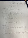
I need to resolve it with 2 procedures: trigonometry and instant centers. My advance can be see in the next image:

Captura de Pantalla 2021-09-14 a la(s) 0.29.12.png


The instant centers procediment its (1) up and trigonometry procediment its (2) down.

I know that the result its 4 rads/s. But in my answer its not make the sense ;( and i don't know why the angular velocity of "D" its 4 rads/s.

PD: I don't can use cross product for resolve it... only trigonometry and instant centers (separately).

Thanks for read ;)
 
Physics news on Phys.org
I would introduce xy coordinate as sketched.
From these linear equations for sin##\phi## and cos##\phi## we can delete ##\phi## and get x, the horizontal coordinate of E, as function of ##\theta## which is function of time.

[EDIT] The formula are written as
(x/2-\cos\phi-\beta)^2+(1-\sin\phi)^2=1/4
(x/2-\cos\phi-\cos\theta)^2+(1-\sin\phi-\sin \theta)^2=1/4
where
\beta=\frac{\sqrt{3}-1}{2}=\frac{1}{\sqrt{3}+1}
Solving this equation for sin##\phi## and cos##\phi## and using the relation
\sin^2\phi+\cos^2\phi=1
The relation of x and ##\theta## is given as
(b_1c_2-b_2c_1)^2+(c_1a_2-c_2a_1)^2=(a_1b_2-a_2b_1)^2...(1)
where
a_1=1
a_2=1-\sin\theta
b_1=\frac{x}{2}+\frac{\sqrt{3}-1}{2}
b_2=\frac{x}{2}-\cos\theta
c_1=\frac{3}{8}+\frac{a_1^2+b_1^2}{2}
c_2=\frac{3}{8}+\frac{a_2^2+b_2^2}{2}
Differentiating (1) by t for t=0 we would know ##\dot{x}(t=0)##. After calculation I got
\dot{x}=-3.017 r\dot{\theta} for initial time t=0, where r is 1 length unit for rods. I do not have trust of my calculation. I should appreciate it if someone would challenge it too.
 

Attachments

  • 2021-09-15 21.16.39.jpg
    2021-09-15 21.16.39.jpg
    32.6 KB · Views: 135
Last edited:
anuttarasammyak said:
I would introduce xy coordinate as sketched.
From these linear equations for sin##\phi## and cos##\phi## we can delete ##\phi## and get x, the horizontal coordinate of E, as function of ##\theta## which is function of time.
yep, i can use a free body diagram, but in this pariticulary case i only can use the procedure as I put it. The most important are the traslation and rotation diagram and the use of angles in triangles.
 
Noob of the Maths said:
yep, i can use a free body diagram, but in this pariticulary case i only can use the procedure as I put it. The most important are the traslation and rotation diagram and the use of angles in triangles.
Hi, I think you should put this into the engineering forum. Does your method allow for sketching velocity diagrams?
 
Master1022 said:
Hi, I think you should put this into the engineering forum. Does your method allow for sketching velocity diagrams?
Yes, velocity diagrams its allowed. Hi :)
 
Noob of the Maths said:
Yes, velocity diagrams its allowed. Hi :)
Cool, so the steps I would think about when going down the velocity diagram route are:
1. A and C are fixed
2. E is constrained to pure horizontal movement, as is D (in this case) as CD is vertical
3. We know ##\omega_{AB}## and thus know where point B is
4. To get from point B to point D, we then know there must be a rotation between the two
5. Then to get from D to E, given that E is constrained to horizontal movement, it suggests to me that ##\omega_{DE} = 0## at this instant. However, you said that the answer is ##\omega_{DE} = 4 ## rad/s, or did I misunderstand what you said?

I hope this rough outline makes sense. I can try to make a sketch a bit later
 
Master1022 said:
Cool, so the steps I would think about when going down the velocity diagram route are:
1. A and C are fixed
2. E is constrained to pure horizontal movement, as is D (in this case) as CD is vertical
3. We know ##\omega_{AB}## and thus know where point B is
4. To get from point B to point D, we then know there must be a rotation between the two
5. Then to get from D to E, given that E is constrained to horizontal movement, it suggests to me that ##\omega_{DE} = 0## at this instant. However, you said that the answer is ##\omega_{DE} = 4 ## rad/s, or did I misunderstand what you said?

I hope this rough outline makes sense. I can try to make a sketch a bit later
This very helpful!, i know that my mistakes its in the diagram and their angles. wDE= 4 rad/s based on assumptions,
 
Consider that:
1) E can only have horizontal movement.
2) Only the horizontal component of the instantaneous velocity of D has influence on E.
3) Because both are connected by a horizontal link, the horizontal components of the instantaneous velocity of D and B must be equal.
4) Since you are given the angular velocity of the 2 feet long link AB, you can calculate the tangential velocity of B and then, its instantaneous horizontal component.
 
anuttarasammyak said:
I should appreciate it if someone would challenge it too.
You are way overthinking it.
It is really quite simple following @Lnewqban's scheme.
 
  • Like
Likes Lnewqban and anuttarasammyak
Back
Top