Find unknown values of current in multi-loop circuit

  • Thread starter Thread starter mhrob24
  • Start date Start date
  • Tags Tags
    Circuit Current
Join the discussion
Ask a follow-up here, or get your own question answered by working scientists, mathematicians and engineers — people, not an autocomplete.
Real named experts · corrections over time · the nuance an AI answer skips
2 replies · 2K views
mhrob24
Messages
53
Reaction score
9
Homework Statement
Assign values to the currents in the circuit schematic
Relevant Equations
V = IR
Kirchhoff's rules
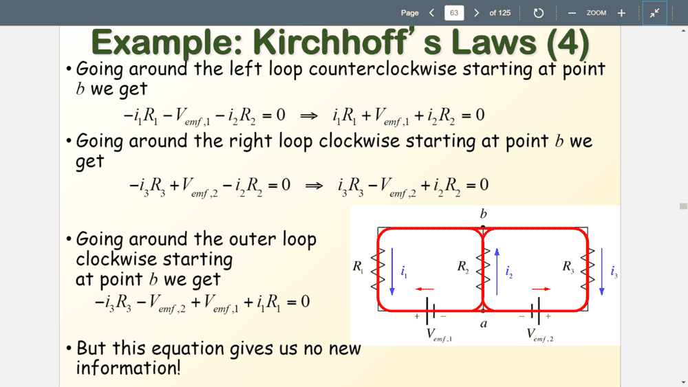
So I'm going over my review questions/notes provided by my professor for the upcoming exam on Tuesday, and I came across an example problem that I THINK might be a typo, but I want to make sure I'm right.
1572112053968.png
I'm not sure why the potential drop when crossing V2 is ADDED to the loop equation for the right loop and not SUBTRACTED. If we're moving clockwise from B, we will cross through the EMF source from the positive to the negative terminal, so the potential should be subtracted from the total potential. Same goes for the left loop when traveling COUNTERclockwise from point b. You will cross through the EMF source V1 from the positive to the negative terminal.
 
Physics news on Phys.org
I agree with his signs for the voltage drops across the batteries..

He is not consistent with his voltage drop signs in the different loops based on the way that he has chosen his currents (btw you only need two). You can choose the currents in any direction you wish but you must be consistent. The convention (as I have always used ) is when you go against the current directions you chose you take the voltage drop as negative and when going from the negative terminal of the battery to the positive it is take and negative and when going from positive to negative you take it as positive. So he is consistent with the signs of the battery voltage drop.

So the first equation is correct although his sign convention is the opposite of mine when going around the left loop.

In the right loop he is inconsistent in his signs for the voltage drop across the resistors compared to the left loop. I disagree with his final equation It should be -i3R3 - i2R2 = V2

In addition you need a node equation for the currents i.e., i1 +13 = i2 , you have three unkowns therefore you need three equat
 
  • Like
Likes   Reactions: mhrob24
gleem said:
In the right loop he is inconsistent in his signs for the voltage drop across the resistors compared to the left loop. I disagree with his final equation It should be -i3R3 - i2R2 = V2

Thank you SO much for clearing that up, honestly. I spent hours trying to figure out how it could be correct. That final equation for the right loop is what was confusing me. Her initial equation for the right loop is :

-i2R2 + V2 - i3R3

and the sign of the V2 is what was confusing me. It should be subtracted since we're crossing over the EMF source from the positive to the negative terminal. So the equation should have been :

-i2R2 - V2 - i3R3 = 0 , or as you put: -i2R2 - i3R3 = V2

Thanks again!