Given force, need to determine what bearing to use for a crane
- Thread starter salamikorv
- Start date
Join the discussion
Registration is free. Ask a follow-up in this thread, or start your own.
69 replies · 7K views
Physics news on Phys.org
salamikorv
- 36
- 2
Thanks a lot i will come back if something is off with the bolts. I'll calculate in a moment.Baluncore said:PCD = Pitch Circle Diameter.Load =1000 * 9.81 newton.
Look at manufacturer's bolt specifications.You need to consider how the bolts are held in the floor, so they do not pull out.
salamikorv
- 36
- 2
Nevermind i had a mistake, its all good.Baluncore said:I do not know which bearing you are specifying.
salamikorv
- 36
- 2
For n=8, PCD=35mm, r=1,5m, and the load=1000*9,81, i get 52,5kN, is that the tension that every bolt have? Isnt that super high? Thats the force on all 8 bolts separately?Baluncore said:PCD = Pitch Circle Diameter.Load =1000 * 9.81 newton.
Look at manufacturer's bolt specifications.You need to consider how the bolts are held in the floor, so they do not pull out.
Science Advisor
2025 Award
- 17,252
- 10,712
But only two or three bolts are holding down the side of the base furthest from the hook, where that moment can be of any real advantage.salamikorv said:Thats the force on all 8 bolts separately?
You mean more like 300 mm.salamikorv said:PCD=35mm
salamikorv
- 36
- 2
Ahh yea thats right hahaha my bad, then i get 6131N with PCD=300mm. I changed the geometry to a circle instead of a square by the way, why cant i have 8 bolts? Does it have to be 2 or 3?Baluncore said:But only two or three bolts are holding down the side of the base furthest from the hook, where that moment can be of any real advantage.You mean more like 300 mm.
Science Advisor
2025 Award
- 17,252
- 10,712
You should use 8 bolts, but depending on the direction of the boom load, most will not be doing any real work.salamikorv said:I changed the baseplate geometry to a circle and not a square. I cant use 8 bolts? Why only 2-3?
The boom is a lever arm trying to overturn the base.
salamikorv
- 36
- 2
I didnt understand the part with the boom load, where is that? Could you maybe draw it? Its not the force coming from the lift?Baluncore said:You should use 8 bolts, but depending on the direction of the boom load, most will not be doing any real work.
The boom is a lever arm trying to overturn the base.
salamikorv
- 36
- 2
I got forces here aswell, do i have to do calculation based on them someway to get the forces acting on each bolt maybe and not only the lift load?
Science Advisor
2025 Award
- 17,252
- 10,712
The load hanging on the hook is not above the centre of the base.salamikorv said:I didnt understand the part with the boom load, where is that? Could you maybe draw it? Its not the force coming from the lift?
Extend the line of the rope downwards, then measure the distance from the vertical axis of the base to that line. That is the radius to the load. That is effectively the boom of the crane.
The moment of the load, at that radius, is countered by the base. Some base forces are downwards, but on the side furthest from the load, the forces are upwards. The two or three bolts on that side are under tension.
I have no idea what is fixed and what is moving there.salamikorv said:I got forces here aswell, do i include them in someway?
You must draw and label a better diagram.
erobz
Gold Member
- 4,504
- 1,862
The load creates a moment ## \circlearrowleft## about the anchor.
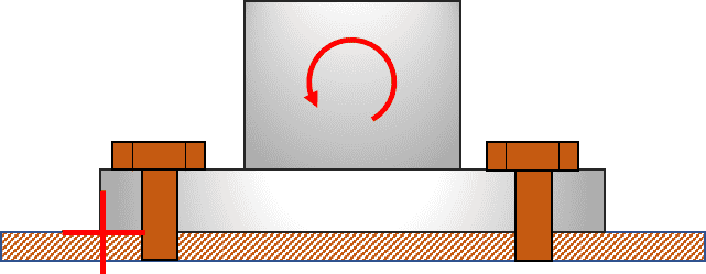
The bolts farther away from the axis of rotation ( ##\color{red}+##) tend to carry more load. Assuming only 2 of the farthest bolts balance the moment builds in a factor of safety.
You balance the moment from the bolts about the axis of rotation against your moment load. Then you use the proof strength of a desired grade bolt and calculated tensile load to calculate bolt cross-section.
The bolts farther away from the axis of rotation ( ##\color{red}+##) tend to carry more load. Assuming only 2 of the farthest bolts balance the moment builds in a factor of safety.
You balance the moment from the bolts about the axis of rotation against your moment load. Then you use the proof strength of a desired grade bolt and calculated tensile load to calculate bolt cross-section.
Last edited:
erobz
Gold Member
- 4,504
- 1,862
What is going on in this calculation?salamikorv said:Another thing, this is for the bearing, i got these calculations and i ended up with 0,7 revolutions....
And the text part is saying "choosing a ball bearing diameter of 35mm from SKF, bearing 16003 with C = 6,37kN" What should i do to fix this and get atleast a million revolutions or higher.View attachment 325008
Please take a moment to learn how to use Latex to format your calculations so we can clearly see them. These grainy images of chicken scratch are annoying for someone trying to help you to interpret.
1) Why are you cutting the bearing load in each direction in half? Are there two bearings in each sheave?
2) For the ##L_{10}## life the units are millions of revolutions. I tried to point that out, it doesn't appear that it has sunk in.
Last edited:
erobz
Gold Member
- 4,504
- 1,862
I'm also suspicious of this force balance. Would share how you obtained them using the free body diagram of the boom?salamikorv said:View attachment 325009
I got forces here aswell, do i have to do calculation based on them someway to get the forces acting on each bolt maybe and not only the lift load?
salamikorv
- 36
- 2
Sorry for the late reply, there's only bending on that point, 15000Nm. So as you can see, the 20kN is in tension and then there's 30kN for the beam in the middle thats 30kN in compression. Do i use those to calculate the tension on each bolt or?erobz said:I'm also suspicious of this force balance. Would share how you obtained them using the free body diagram of the boom?
erobz
Gold Member
- 4,504
- 1,862
Where is your free body diagram of the beam?salamikorv said:Sorry for the late reply, there's only bending on that point, 15000Nm. So as you can see, the 20kN is in tension and then there's 30kN for the beam in the middle thats 30kN in compression. Do i use those to calculate the tension on each bolt or?View attachment 325315
View attachment 325310View attachment 325311
salamikorv
- 36
- 2
My mate is responsible for the calculations of the beam, and he got that, so what i have for the bottomplate is thiserobz said:Where is your free body diagram of the beam?
erobz
Gold Member
- 4,504
- 1,862
Well, are you not able to do a FBD of the beam? It's always a good idea to check each other, and in this case I think it probably a really good idea.salamikorv said:My mate is responsible for the calculations of the beam, and he got that, so what i have for the bottomplate is thisView attachment 325317
salamikorv
- 36
- 2
I can but i dont have time to set my mind into doing the calculations for the beams, using s235, finding out the stresses for it, its going to take a lot of time its not that easy. Whats important for my part is to determine the right bolts, and he gave me the forces thats acting on the plate and im not sure how to determine what bolts to use since those two forces act towards the middle point. Do you have an idea of what do to with those two forces to determine the right bolts? @Baluncore any ideas? I dont think i can use the formula you gave me before, it cant be that easy.erobz said:Well, are you not able to do a FBD of the beam? It's always a good idea to check each other, and in this case I think it probably a really good idea.
erobz
Gold Member
- 4,504
- 1,862
You must get the correct forces before you can get the correct bolts. I'm not asking you to do the shear and moment diagrams for the beam, just a free body diagram of the forces acting on that beam.salamikorv said:I can but i dont have time to set my mind into doing the calculations for the beams, using s235, finding out the stresses for it, its going to take a lot of time its not that easy. Whats important for my part is to determine the right bolts, and he gave me the forces thats acting on the plate and im not sure how to determine what bolts to use since those two forces act towards the middle point. Do you have an idea of what do to with those two forces to determine the right bolts? @Baluncore any ideas? I dont think i can use the formula you gave me before, it cant be that easy.
salamikorv
- 36
- 2
They are correct, the forces he got is correct as our supervisors has checked them for us. If you can assume they are correct, how do i get the bolt tension?erobz said:You must get the correct forces before you can get the correct bolts. I'm not asking you to do the shear and moment diagrams for the beam, just a free body diagram of the forces acting on that beam.
erobz
Gold Member
- 4,504
- 1,862
I'm sensing this is a school project.berkeman said:What supervisors? Is this for a schoolwork project? Or are you tasked with doing this in real life at work?
salamikorv
- 36
- 2
Yea its a school project, no its not for real life work. We get help from the studentassistents in the lectures all the time. They give us direct methods that we can use to make our parts, thats how i determined the bearings because its thanks to them. But ive been sick this week, still i am, so i havent been able to go to school and ask for help and its been difficult to understand how i can get the tension for the bolts when i have two forces directed in two different directions.berkeman said:What supervisors? Is this for a schoolwork project? Or are you tasked with doing this in real life at work?
erobz
Gold Member
- 4,504
- 1,862
Maybe I'm missing something or inferring too much about dimensions. Lets try a sanity check to see if that is indeed the loading on your base. Apply the loads your supervisors tell you are correct. Is the beam in equilibrium?
salamikorv
- 36
- 2
Yes it is.erobz said:View attachment 325318
Maybe I'm missing something or inferring too much about dimensions. Lets try a sanity check to see if that is indeed the loading on your base. Apply the loads your supervisors tell you are correct. Is the beam in equilibrium?
erobz
Gold Member
- 4,504
- 1,862
what are the missing dimensions?salamikorv said:Yes it is.
salamikorv
- 36
- 2
1.5m to the left, i mean thats the length from the left end of the beam to the point where you drew the upward force, and 0.75m is the length thats lefterobz said:what are the missing dimensions?
erobz
Gold Member
- 4,504
- 1,862
Explain how its in static equilibrium with an unbalanced horizontal force component from the support and the tension on the pulley?salamikorv said:1.5m to the left and 0.75m to the right