What original position? Are you basing that on a diagram provided with the question?
If so, I would think it is purely illustrative of a general position, not indicating any specific angles of interest.
What angle, or difference of two angles, do you consider to be the 'throw', and what value do you get for it?
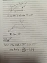
After some research, it seems that the "transmission angle" is BCD in your diagram. I'm still unclear what the "maximum pressure angle" is, but I here assume it is a particular value of the transmission angle, namely, that which corresponds to maximum pressure somewhere.
You wrote that it corresponds to the minimum transmission angle, so if my assumption is correct it would be that minimum value.
However, my intuition is that it means an angle at which the maximum pressure is exerted on joint C, and that would be when ABC is a straight line, yes?
In the actual setup, it can go past straight, making the transmission angle smaller.
Can you provide a link where all these terms are defined?