Heat pump efficiency calculations - Compressor power issue

Join the discussion
Ask a follow-up here, or get your own question answered by working scientists, mathematicians and engineers — people, not an autocomplete.
Real named experts · corrections over time · the nuance an AI answer skips
23 replies · 4K views
Martin Harris
Messages
102
Reaction score
6
The heat pump comprises of the 4 components: evaporator, compressor, condenser and expansion valve.

Thermal power required to heat the building: 12.1 kW at condensing temperature tc = 44.3 deg C
For the evaporator: vaporizing temperature tv = -7 deg C
Subcooling temperature for the heat pump Δ tsc = 5 deg C
adiabatic coefficient: k = 1.16
vaporising pressure: pv =t(tv) =paspiration =4bar
condensing pressure: pc = t(tc) = pdischarge =17bar
vapor density: ρv=17.0 kg/m3
specific volume for aspiration vaspiration = 1/ρv = 1/17kg/m3 = 0.058823529 m3/kg
internal compressor efficiency: ηi=0.84
h1= hv(tv) = 402.56 kJ/kg
h3 =hl(tsc,pc) =248.6 kJ/kg

Now I tried finding out the following:
a)Thermal power Q0 at the evaporator
b)Compressor power
c)efficiency of the heat pump (both COP and refrigeration cycle efficiency ε )

a)Q0=q0*mrf, where q0 = specific heat load, and mrf=mass floware for the refrigerant

q0 = h1-h4 = h1-h3; because h3=h4
so q0 = 402.56 kJ/kg - 248.6 kJ/kg => q0 = 153.96kJ/kg

compressor work: compressor_work = (k/((k-1)*ηi))*paspiration*vaspiration*((pdischarge/paspiration)^((k-1)/k)-1)*100
compressor_work = 44.85735668 kJ/kg

enthaply in the 2nd point: h2 = h1+compressor_work = 402.56 kJ/kg+44.85735668 kJ/kg
h2 = 447.4173567 kJ/kg

specific heat load at the condenser: qc = h2-h3 = 447.4173567 kJ/kg - 248.6 kJ/kg
qc =198.8173567 kJ/kg

so: mrf = Qc/qc = 12.1 kW/198.8173567 kJ/kg
mrf = 0.060859878 kg/s (refrigerant mass flowrate)

Thermal power Q0 at the evaporator: Q0=q0*mrf
Q0 = 153.96kJ/kg*0.060859878 kg/s
Q0 = 9.369986761 kW

b)Compressor_power = (mass_flowrate_refrigerant * compressor_work) / (ηmotor*ηelectrical)
Problem arises here because I was given just the internal efficiency ηi=0.84, but the formula uses the efficiency of the motor ηmotor and the electrical efficiency ηelectrical...so how can I calculate this? (as I don't have the ηmotor*ηelectrical), I don't want to guess though...

c)COP =qc/work_compressor = 198.8173567 kJ/kg / 44.85735668 kJ/kg
COP = 4.432
ε = heat load evaporator/work done = COP - 1 = 3.432

What do you think of the calculations, do they make any sense? I'd really appreciate a peer review.

My actual question is, how can I calculate the compressor power at b) as I don't have those 2 efficiencies (ηmotor and ηelectrical), but just the ηi which is the internal efficiency of the compressor?
 
Engineering news on Phys.org
Martin Harris said:
My actual question is, how can I calculate the compressor power at b) as I don't have those 2 efficiencies (ηmotor and ηelectrical), but just the ηi which is the internal efficiency of the compressor?
I don't have time to check the calcs right now, but based on what was given, they are probably asking for the mechanical power, not electrical.
 
  • Like
Likes   Reactions: Martin Harris and Lnewqban
Hi,
Thanks for the reply, I was given just the actual internal efficiency for the compressor.
Is there any way to calulate the compressor power with just the data I have, without having mechanical and electrical efficiencies?
 
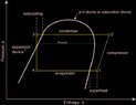
Please find below a schematic diagram if it is of any help.
The heat exchangers have plates and are using water and refrigerant.
 

Attachments

  • Schematic Diagram.jpg
    Schematic Diagram.jpg
    29.8 KB · Views: 284
Last edited:
This pertains to the work done on the working fluid in the compressor.

If I use the isentropic equations for k = 1.16, I get a temperature of 52.4 C exiting the compressor and an enthalpy increase of 37.7 kJ/kg in the compressor. If I use the thermodynamic tables for R22, I get a temperature of 67.9 C exiting the compressor and an enthalpy increase of 36.5 kJ/kg in the compressor. So, either way, the work done on the refrigerant is about 37 kJ/kg in the compressor. Assuming an isentropic efficiency of 0.84, doing it the first way, I confirm your value of 44.8 kJ/kg for the enthalpy change and the work.

I also confirm your determination of the mass flow rate.
 
  • Like
Likes   Reactions: russ_watters
Thank you!
All right, in this case, how can those be calculated then with the data I was given? I have my attempt in post#1, but still can't do the compressor power because I don't have the motor and electrical efficiencies, just the internal compressor efficiency which was used to calculate the work for the compressor.
 
Last edited:
Hi,
Right, okay. So can we say that compressor power = mass flowrate of refrigerant * specific work for the compressor?
 
If I'm asked to plot a log p-h diagram for the following statement:

"A building needs a thermal power for heating Q = 12 [kW] at with a condensing temperature tc = 44.3 deg C, the heating being performed with heat pump. The heat source is represented by the soil. The installation works with a refrigerant whose vaporization temperature is tvap = -7 deg C. The degree of subcooling of the installation ΔtSC = 5 deg C."

So for this case on the log p-h diagram I should plot just the sub-cooling part, right? I wasn't told anything about superheating.

The question is...can we have sub-cooling without super-heating though?
So should I plot just the sub-cooling process on the log p-h diagram? Or should I plot both sub-cooling and superheating on the log p-h diagram?

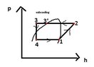
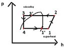
Should the log p-h diagram be like Fig.1 or like Fig.2? (please see below)
 

Attachments

  • Fig1.png
    Fig1.png
    2.2 KB · Views: 244
  • Fig2.jpg
    Fig2.jpg
    48.9 KB · Views: 247
Last edited:
Hi, thanks for the quick reply, I do appreciate it.

The problem is that I have to plot the p-h diagram for the heat pump myself, but not sure if I should have just the subcooling process since I was given just the subcooling degree "It is known that the degree of subcooling of the heat pump ΔtSC = 5 deg C."

Or should I have both sub-cooling and super-heating, though the word superheating was not specified within the text...that got me confused, is it possible to have just subcooling without superheating for the heat pump?

"A building needs a thermal power for heating Q = 12 [kW] at with a condensing temperature tc = 44.3 deg C, the heating being performed with heat pump. The heat source is represented by the soil. The installation works with a refrigerant whose vaporization temperature is tvap = -7 deg C. The degree of subcooling of the heat pump is known such as ΔtSC = 5 deg C."

Don't know if to plot the p-h diagram just with the sub-cooling or with both sub-cooling and superheating, based on the text provided above.

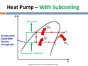
Anyway, for the coolant (R22) I assume the log p-h diagram is something like this:
1619113237312.png
 
Last edited:
  • Like
Likes   Reactions: Chestermiller
Thank you for your logical response.

I've been given some additional data:

internal efficiency for the compressor: 0.84

pv(vaporizing pressure) = t(tv) = 4bar

pc(condensing pressure)=t(tc)=17 bar

ρv=17 kg/m3

h1=hv(tv)=402.56 kJ/kg, where tv = vaporizing temperature, yet it doesn't say anything about tsh (superheating temperature)

h3=h1(tsc,pc)=248.6 kJ/kg, where tsc=subcooling temperature, pc=condensing pressure

k=1.16 (adiabatic index)

Yet again, superheating is not specified, so I guess, it's just subcooling, right?
 
Last edited:
Martin Harris said:
Thank you for your logical response.

I've been given some additional data:

internal efficiency for the compressor: 0.84

pv(vaporizing pressure) = t(tv) = 4bar

pc(condensing pressure)=t(tc)=17 bar

ρv=17 kg/m3

h1=hv(tv)=402.56 kJ/kg, where tv = vaporizing temperature, yet it doesn't say anything about tsh (superheating temperature)

h3=h1(tsc,pc)=248.6 kJ/kg, where tsc=subcooling temperature, pc=condensing pressure

k=1.16 (adiabatic index)

Yet again, superheating is not specified, so I guess, it's just subcooling, right?
When you compress the saturated vapor that enters the compressor, the vapor is compressed isentropically and exits the compressor in a superheated state at 17 bars and about 70 C. So it enters the condenser superheated and exits sub-cooled.
 
  • Like
Likes   Reactions: Martin Harris
Chestermiller said:
When you compress the saturated vapor that enters the compressor, the vapor is compressed isentropically and exits the compressor in a superheated state at 17 bars and about 70 C. So it enters the condenser superheated and exits sub-cooled.
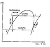
Right, okay. So, now with the actual given data if I'm asked to plot a log p-h diagram for the entire heat pump, it should resemble the one like in Fig.1, right? Just the subcooling part basically, because superheating (before entering the compressor 1-1') was not stated anywhere within the text. When I am speaking about superheating I am referring to the one before entering the compressor. I currently don't know based on the provided data if the p-h diagram should include the superheated process right before entering the compressor, given that the input data (text) hasn't specified anything about superheating.

So how should the log p-h diagram look like for the heat pump?
 
Last edited:
Hi

Thanks for your reply.
Like I should not have superheated process 1-1' before entering the compressor.

I am trying to understand why I was not given any information on purpose regarding the superheated process before entering the compressor.

So, the p-g diagram, should look something like this, right? (please see below)
 

Attachments

  • Fig3.jpg
    Fig3.jpg
    45 KB · Views: 268
  • Fig4.jpg
    Fig4.jpg
    16.2 KB · Views: 227
Last edited:
Martin Harris said:
Hi

Thanks for your reply.
Like I should not have superheated process 1-1' before entering the compressor.

I am trying to understand why I was not given any information on purpose regarding the superheated process before entering the compressor.

So, the p-g diagram, should look something like this, right? (please see below)
I don't know what 1-1' means. But, in any case, Fig. 4, not Fig. 3
 
  • Like
Likes   Reactions: Martin Harris
Hi,

Thanks for the reply.

Please see Fig.5 and Fig.6 below, where 1->2 compressor, 2->3 condenser, 3->4 expansion valve, 4->1 evaporator.

Which one would you say that is now the correct p-h diagram for the above given data for the heat pump?
 

Attachments

  • Fig5.JPG
    Fig5.JPG
    7.8 KB · Views: 244
  • Fig6.JPG
    Fig6.JPG
    16.7 KB · Views: 243
Thank you for your quick reply, really much appreciated!

Yeah right, absolutely, it makes sense to enter as saturated vapor in the compressor, yet I am afraid that if it won't be superheated the compressor might corrode due to liquid droplets, but then again, I was not told anything about superheated vapors.
 
Can we say that the efficiency for the refrigeration cycle for the heat pump = COP -1 ?

I know that usually the refrigeration cycle efficiency = Qevaporator/Work done by compressor