Zardichar
- 2
- 0
Hey guys, I am new to the forum and came to here to ask for help on a project that I am trying to construct.
I have 3 lithium polymer batteries, one 7.4v, 11.1v, and 14.8v. The current draw will be around 150a for an extremely short period of time (a couple milliseconds) and then will settle to around 30a continuous.
I want to use a 1 pole, 4 position (1 for off) rotary switch, but none of them can sustain very high currents. So that is where I need your help.
I made the following circuit for it: (sorry for low quality)
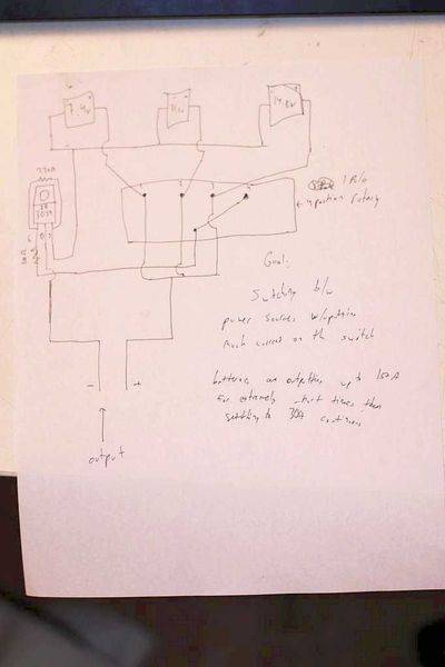
but I quickly realized that when the switch is turned to any of the positions, then the higher voltage battery would just dump current into the other two, so that would be very, very bad.
I was advised to use SSR's, but then, after looking up the prices on them, decided that it wouldn't really be feasible due to my low budget ($75) Maybe there is a way to imitate the function of an SSR with just MOSFETs? I don't need it to function with AC nor do I need complete isolation so that is why I am trying to favor MOSFETs.
Please correct anything that is wrong in this post and please help me with this project.
All comments are welcome and I thank you guys in advance!
I have 3 lithium polymer batteries, one 7.4v, 11.1v, and 14.8v. The current draw will be around 150a for an extremely short period of time (a couple milliseconds) and then will settle to around 30a continuous.
I want to use a 1 pole, 4 position (1 for off) rotary switch, but none of them can sustain very high currents. So that is where I need your help.
I made the following circuit for it: (sorry for low quality)
but I quickly realized that when the switch is turned to any of the positions, then the higher voltage battery would just dump current into the other two, so that would be very, very bad.
I was advised to use SSR's, but then, after looking up the prices on them, decided that it wouldn't really be feasible due to my low budget ($75) Maybe there is a way to imitate the function of an SSR with just MOSFETs? I don't need it to function with AC nor do I need complete isolation so that is why I am trying to favor MOSFETs.
Please correct anything that is wrong in this post and please help me with this project.
All comments are welcome and I thank you guys in advance!
Last edited: