Tolklein
- 45
- 19
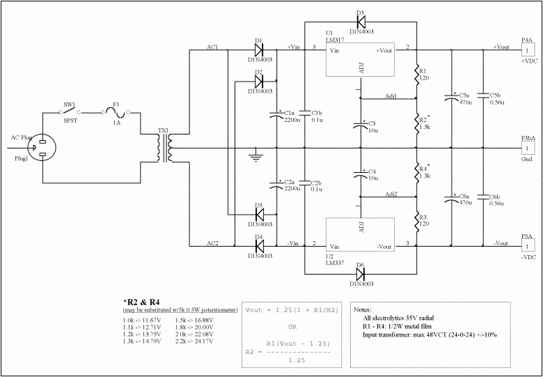
So many moons ago I made myself a pretty bog standard dual linear bench power supply using an LM317 and LM337 to give me -15 - 0 - +15.
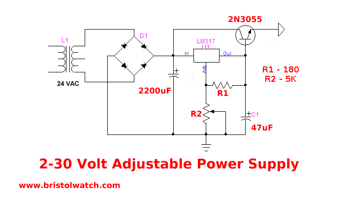
In an attempt to get more current out of it (for no real reason other than because I can) I got a larger transformer and a beefier rectifier, then using the ever faithful 2N3055 and a pretty standard schematic managed to get a good 5amps out of the positive rail.
However modifying the negative rail has pushed my googling skills to the limit, and I'm at a loss as to how to go about modifying the existing LM337 circuit to also boost the final current output.
Any advise or suggestions on where to look would be greatly appreciated.
P.S.
Attached images are more or less what I'm referring to, the first pretty much being what I had, and the second, what I've achieved, on the positive side anyway...
In an attempt to get more current out of it (for no real reason other than because I can) I got a larger transformer and a beefier rectifier, then using the ever faithful 2N3055 and a pretty standard schematic managed to get a good 5amps out of the positive rail.
However modifying the negative rail has pushed my googling skills to the limit, and I'm at a loss as to how to go about modifying the existing LM337 circuit to also boost the final current output.
Any advise or suggestions on where to look would be greatly appreciated.
P.S.
Attached images are more or less what I'm referring to, the first pretty much being what I had, and the second, what I've achieved, on the positive side anyway...