How Do Basic Capacitor Concepts Affect Voltage in Simple Circuits?

5 replies · 3K views · last reply
skybox
Messages
37
Reaction score
0
Hi Guys,

I have the following circuit I want to analyze:
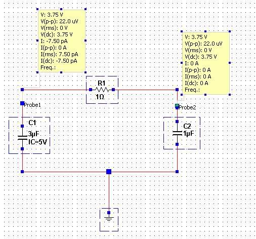
Circuit schematic in a simulator: C1 (3µF, IC=5V) on the left and C2 (1µF) on the right, joined through resistor R1 (1Ω) on top with the bottom wire grounded; two yellow probe readouts show V 3.75 V, I values in pA, and Freq. blank.


I do not understand by the DC voltage on both capacitors is 3.75V each. The initial charge on capacitor C1 is 5V. I am just trying to understand a basic switched capacitor concept and am stuck here. Any insight would be greatly appreciated!
 
Hello,

Are your measurements at t=0s or some other time? I would suggest adding a switch to your schematic.
 
Yes, you must be measuring at some intermediate time.
The fact that there is dissipation (a resistor) but no source in the circuit means that the voltage will eventually go to zero regardless of the initial state.
 
I am measuring the voltage at t = 60s. I am just wondering how it is 3.75V. I am modeling this circuit after a switch has closed.
 
skybox said:
I am measuring the voltage at t = 60s. I am just wondering how it is 3.75V. I am modeling this circuit after a switch has closed.

You initially had 5V on the left 3uF cap, and after the switch is closed (presumably the 1 Ohm resistor), you have 3.75V on both the 3uF and 1uF caps. Seems pretty straightforward. Do a time plot from 0s to 60s of the voltages on the caps, and you'll see the chage distribution change from initial to final.
 
Before the switch is closed, there is 15 microcoulombs on the capacitor C1 (3 uF), which is charged to 5 V. After the switch is closed, you have 15 microcoulombs on 4 uF (C1 + C2 in parallel), so the voltage should be reduced to 3.75 volts. So charge is conserved. Initially the total stored energy in the circuit is (1/2)CV^2 = 37.5 microjoules, and after the switch is closed, the stored energy is only 28.1 microjoules, so some energy was lost in resistance R1 when the switch was closed.