How Do Multiple Wires Affect Stress Distribution in Steel Brackets?

  • Thread starter Thread starter DYLAN4321
  • Start date Start date
  • Tags Tags
    Steel Stress
AI Thread Summary
The discussion centers on calculating stress distribution in steel brackets affected by multiple wires. A user has developed catenary software to analyze tension forces and is seeking guidance on stress calculations for various attachment methods. Key stress factors include bolt shear, compressive failure, shear failure, and tension failure around attachment holes. The complexity of stress distribution in brackets is highlighted, with references to established design theories and codes for safe construction practices. Following standard procedures is emphasized to avoid unsafe outcomes in design.
DYLAN4321
Messages
4
Reaction score
0
TL;DR Summary
Plate with hole help
Hi,

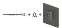
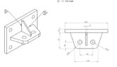
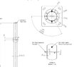
I have developed a catenary software that calculates the tension force resulting from the wire and now I am working on suitable fixing methods and including the option for this within the software.

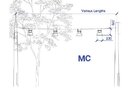
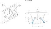
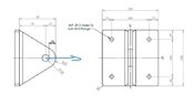
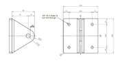
Has anyone got any guidance on working out the stresses applied on the attached applications? Also how woudl the circular plate act if there were multiple wires pulling in different directions?

I have done a quick mock up for a plate with multiple holes, but this isn`t really applicable to these applciations given the holes are positioned close to the edge of the plates.

Any help will be appreciated
 

Attachments

  • Example A.jpg
    Example A.jpg
    20 KB · Views: 155
  • Example B.jpg
    Example B.jpg
    26.7 KB · Views: 140
  • Example C.jpg
    Example C.jpg
    19.6 KB · Views: 154
Last edited:
Engineering news on Phys.org
Welcome!
It is difficult for me to make sense of the wires you mention and the three attached drawings.
Could you explain the assembly a little more?
Thank you.
 
Hello,

Thank you for your reply.

I have attached an image of an example of the mounting arrangement. Basically a Dee shackle fits through the hole in the plate and then the turnbuckle with the centenary wire is fitted to the shackle.

Thanks
 

Attachments

  • Catenary Mounting Arrangement.jpg
    Catenary Mounting Arrangement.jpg
    12.3 KB · Views: 138
  • Example Mounting.jpg
    Example Mounting.jpg
    21.7 KB · Views: 130
Sorry, I am still lost; perhaps another member will be able to help.
 
Thanks anyway.

I have attached another sketch which shows the direction of the tension force applied.

Say as an arbitrary force of 1kN applied in all directions?
 

Attachments

  • Example A Force Direction.jpg
    Example A Force Direction.jpg
    22.6 KB · Views: 128
  • Example B Force Direction.jpg
    Example B Force Direction.jpg
    30.6 KB · Views: 113
  • Example C Force Direction.jpg
    Example C Force Direction.jpg
    20.2 KB · Views: 138
Several cases need to be calculated when designing brackets. For the region around the attachment holes, the following need to be calculated:
1) Bolt shear
2) Compressive failure in bracket
3) Shear failure in bracket
4) Tension failure in bracket

The rest of the bracket is complex. The following quote from my copy of Manual of Steel Construction, 9th Edition illustrates the point:

The actual distribution of stress in the tee flange or angle leg and the extent of prying action are extremely complex. ... Good correlation between estimated connection strength and observed test results has been obtained using theory of Ref. 1. Design and analysis procedures based on this theory have been developed in Refs. 2 and 3.

I recommend that you study the CE Machinery Directive and applicable codes relevant to steel construction in your country. The codes have standard procedures for designing connections that result in safe connections. Those standard procedures have been tested and are proven to work. Trying to do your own analysis is what we call "reinventing the wheel", and can lead to unsafe results.
 
How did you find PF?: Via Google search Hi, I have a vessel I 3D printed to investigate single bubble rise. The vessel has a 4 mm gap separated by acrylic panels. This is essentially my viewing chamber where I can record the bubble motion. The vessel is open to atmosphere. The bubble generation mechanism is composed of a syringe pump and glass capillary tube (Internal Diameter of 0.45 mm). I connect a 1/4” air line hose from the syringe to the capillary The bubble is formed at the tip...
Thread 'Physics of Stretch: What pressure does a band apply on a cylinder?'
Scenario 1 (figure 1) A continuous loop of elastic material is stretched around two metal bars. The top bar is attached to a load cell that reads force. The lower bar can be moved downwards to stretch the elastic material. The lower bar is moved downwards until the two bars are 1190mm apart, stretching the elastic material. The bars are 5mm thick, so the total internal loop length is 1200mm (1190mm + 5mm + 5mm). At this level of stretch, the load cell reads 45N tensile force. Key numbers...
I'd like to create a thread with links to 3-D Printer resources, including printers and software package suggestions. My motivations are selfish, as I have a 3-D printed project that I'm working on, and I'd like to buy a simple printer and use low cost software to make the first prototype. There are some previous threads about 3-D printing like this: https://www.physicsforums.com/threads/are-3d-printers-easy-to-use-yet.917489/ but none that address the overall topic (unless I've missed...
Back
Top