How do old-timey radio buttons work?

  • Thread starter DaveC426913
  • Start date
  • Tags Tags
    Radio
15 replies · 10K views · last reply
DaveC426913
Gold Member
2025 Award
Messages
24,757
Reaction score
9,178
Back when dinosaurs roamed the Earth, every car had a push-button radio like this:
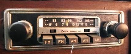
Vintage car radio with a horizontal tuning dial showing FM and AM bands, five black pushbuttons labelled FM, FM, AM, AM, AM, and round knobs on each side.

You pushed a button and the dial would zoom to the preset location.
To set a location, you would manually dial to the right location, then pull the button out, then push it in.

I had set my sights on figuring this out from first principles - perhaps examining on old radio from the local electronics surplus store but never got around to it.

My pride to figure this out on my own has waned, and now I just want to know what I was missing.

How does the mechanism work?
 
Attachments
  • Vintage car radio with a horizontal tuning dial showing FM and AM bands, five black pushbuttons labelled FM, FM, AM, AM, AM, and round knobs on each side.
    car-radio-buttons.jpg
    14.1 KB · Views: 3,274
I'm old enough to remember that the tuning knob moved a string loop that wrapped around the shaft of a rotating variable capacitor. The buttons moved the string, but I don't remember how they recorded the position.
 
anorlunda said:
I'm old enough to remember that the tuning knob moved a string loop that wrapped around the shaft of a rotating variable capacitor. The buttons moved the string, but I don't remember how they recorded the position.
Yep, That's about my understanding too.

It was the 'setting' part that got me.
 
Pull button, releasing string, snap button closed on new setting. One way; seems to my recollection(s), there were a couple other mechanisms.
 
Hand-drawn sketch of a radio pushbutton tuning mechanism, labelled RODS, PULLEY FOR DIAL CORD, ROTATION AXIS, approx. ±45°, BLADE (PIVOTS), PUSH BUTTON and FRONT.


When manual tuning is done, the dialcord rotates the funny cage assembly consisting of two rods between end plates.
Pulling the pushbutton out releases a brake on the blade allowing the blade to pivot.
When the pushbutton is pushed, the blade rotates to match the two bars on the cage assembly.
Further force on the pushbutton engages the brake on the blade, not allowing further rotation.
To tune to another preset station, the appropriate pushbutton is operated, forcing its blade against the rotatable cage assembly, pulling the dialcord to the preset position.
MAGIC! You now are now tuned to the new station.

EDIT: Clarification from post #12 below (thanks to @DaveC426913 for point this out):
The diagonally oriented part to the upper right is the front view of the 'funny cage assembly' (in the real world it is horizontal ). The rest is a view from the left side of the radio.
The left-most piece in the dwg. is the left end of 'funny cage'.

Cheers,
Tom
 
Attachments
  • Hand-drawn sketch of a radio pushbutton tuning mechanism, labelled RODS, PULLEY FOR DIAL CORD, ROTATION AXIS, approx. ±45°, BLADE (PIVOTS), PUSH BUTTON and FRONT.
    upload_2018-10-2_20-40-20.png
    24.8 KB · Views: 2,154
Last edited:
Greg Bernhardt said:
I feel like @dlgoff would know :)
I've seen the string type that rotates a variable capacitor for changing the frequency of a tuning oscillator. I looked around for an old car radio but could only find this set of push-buttons from, IRC, an old table-top radio. With this type, each button switches in different LC tuning circuits. The switches circuit board is made of a Phenolic Paper material which is a type of Bakelite. Note that the buttons have windows where labels of the station's call-sign can be inserted.

Photo of a mechanical push-button tuning assembly from an old radio: a row of six rusty, brown push-button caps with paper station labels visible in their windows, on metal rods above a rusted metal bracket and a board with tubular components and wiring.

Close-up of a vintage radio push-button switch assembly with five brass-contact tuning sections, green and yellow-banded resistors or coils, a round brown coil, and a row of brown plastic push-button housings above.


The mechanical mechanism is rather complicated but still works, sort of:

Close-up photo of a row of old push-button mechanism on a radio, with four brown Bakelite-style buttons above a white plate with a rectangular label window, mounted in a vise.


I know I have an old push-button car radio somewhere. I'll keep looking.
 
Attachments
  • Photo of a mechanical push-button tuning assembly from an old radio: a row of six rusty, brown push-button caps with paper station labels visible in their windows, on metal rods above a rusted metal bracket and a board with tubular components and wiring.
    push1.jpg
    50.6 KB · Views: 1,503
  • Close-up of a vintage radio push-button switch assembly with five brass-contact tuning sections, green and yellow-banded resistors or coils, a round brown coil, and a row of brown plastic push-button housings above.
    push2.jpg
    36.9 KB · Views: 1,564
  • Close-up photo of a row of old push-button mechanism on a radio, with four brown Bakelite-style buttons above a white plate with a rectangular label window, mounted in a vise.
    radiopush.gif
    1.5 MB · Views: 1,658
Last edited:
  • Like
Likes   Reactions: Bystander, Greg Bernhardt and jim mcnamara
This suggests a fun thread that might get wide participation.

"Mechanical replacements for familiar electric gadgets."

Years ago it would have been, "Electric replacements for familiar mechanical gadgets." But today, I think the "familiar" balance has flipped.

There is also "Digital replacements for familiar gadgets." But we already did that under https://www.physicsforums.com/threads/what-do-smart-phones-partially-replace.932077/
 
In AM only radios I believe it was typically variable inductors that did the tuning.
 
  • Like
Likes   Reactions: Tom.G
Tom.G said:
View attachment 231588

When manual tuning is done, the dialcord rotates the funny cage assembly consisting of two rods between end plates.
Pulling the pushbutton out releases a brake on the blade allowing the blade to pivot.
When the pushbutton is pushed, the blade rotates to match the two bars on the cage assembly.
Further force on the pushbutton engages the brake on the blade, not allowing further rotation.
To tune to another preset station, the appropriate pushbutton is operated, forcing its blade against the rotatable cage assembly, pulling the dialcord to the preset position.
MAGIC! You now are now tuned to the new station.

Cheers,
Tom
Thanks. I'm mostly there.
I'm having trouble divining orientation from your beautiful diagram. It's hard to tell the difference between discrete parts and different views of the same part.
 
A system similar to the one described by @Tom.G :

Three-part diagram of a mechanical push-button tuning mechanism: A and B show a rocker arm with a slot, plunger, finger and gear segment in two positions; C is a perspective view of a multi-button unit with push buttons, tuning condenser, gear segment, locking screw, pivot plate and movement-limiting fingers labelled.

The diagrams at A and B show one of the finger and rocker units used in the mechanical automatic tuning systems of some Crosley receivers (including the Crosley Safety-Tune auto radio), while the sketch at C shows the complete tuning unit with a gear drive to a gang tuning condenser. Tightening the screw on the plunger locks the finger rigidly in position. To set up a button for a station, this screw is loosened so the finger can rotate, the button is pushed all the way in, the station is tuned in manually, and the screw is tightened to lock the finger at the correct angle. A spring returns the button to its normal position when pressure is released, leaving the tuning condenser at the correct setting for the desired station.

Other systems descriptions can be found from the source of this quote.
 
Attachments
  • Three-part diagram of a mechanical push-button tuning mechanism: A and B show a rocker arm with a slot, plunger, finger and gear segment in two positions; C is a perspective view of a multi-button unit with push buttons, tuning condenser, gear segment, locking screw, pivot plate and movement-limiting fingers labelled.
    profit-reprogram-pushbuttons-national-radio-news-jun-jul-1940-5.jpg
    59.4 KB · Views: 2,131
  • Like
Likes   Reactions: dlgoff
DaveC426913 said:
Thanks. I'm mostly there.
I'm having trouble divining orientation from your beautiful diagram. It's hard to tell the difference between discrete parts and different views of the same part.
Yeah, not as clear as it could be. :sorry:

The diagonally oriented part to the upper right is the front view of the 'funny cage assembly' (in the real world it is horizontal ). The rest is a view from the left side of the radio.
The left-most piece in the dwg. is the left end of 'funny cage'.

Clarification duly added to post #6.
 
Averagesupernova said:
In AM only radios I believe it was typically variable inductors that did the tuning.

In both my '49 Buick and '53 Ford that was indeed the case. I'm not sure why but i think it had to do with the proneness of those variable capacitors to trap dust in their plates and detune.
In those days car radios were made for extreme sensitivity so that you could get decent reception far away from the cities.
To that end most had a tuned RF stage ahead of the mixer, meaning you'd need a three or four gang tuning capacitor.
Probably it was quicker to manufacture using pre-adjusted tunable inductors instead.

My Ford radio had a single ended 6V6 pentode audio output stage that was adequate - probably around five watts.
The Buick (a Roadmaster), being an upscale car used two 6V6's in push pull . Judging by output transformer size i'd guess it was good for fifteen watts. That would be the envy of tubophiles today.

I saw one of those radios recently in a junkpile - should have picked it up just to salvage its output transformer.
Sigh, something told me to snag it and if i had i could answer your question about the pushbuttons...

old jim
 
  • Like
Likes   Reactions: dlgoff
jack action said:
A system similar to the one described by @Tom.G :

Other systems descriptions can be found from the source of this quote.

Ohhh. Now I see it.

And now I see it in Tom G's diagram.

The only thing I can't quite make out is the brake release. I think the brake is (G), and it presses on the finger, holding its setting. When you pull the button out, it releases the brake, so that the finger can rotate freely. Then you push it in, the finger is set by the pivot plate (F) and the brake is reapplied.

Man, I wish I had some simple animation software. I'd animate this.
 
jim hardy said:
In both my '49 Buick and '53 Ford that was indeed the case. I'm not sure why but i think it had to do with the proneness of those variable capacitors to trap dust in their plates and detune.
I recall being told in school that the reason was dust.
 
jim hardy said:
I saw one of those radios recently in a junkpile - should have picked it up just to salvage its output transformer.
Should have picked it up to restore. :oldgrumpy:
 
  • Like
Likes   Reactions: jim hardy