skaterbasist
- 13
- 0
I passed my statics course and am currently taking material stength course.
The thing that has been on my head is the fact that, although I know how to do shear and bending moment diagrams... I do not know how to READ them. In other words, the diagrams don't mean anything to me.
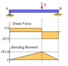
For example, in the diagram below, the maximum moment is being developed under what axis? The z-axis perpendicular to the A support or the z-axis perpendicular to the B support?
I'm not even sure if my question makes any sense. It just bugs me to know that I know how to SOLVE these problems and develop the diagrams, but they're practically meaningless to me.
ANY help would be greatly appreciated!
The thing that has been on my head is the fact that, although I know how to do shear and bending moment diagrams... I do not know how to READ them. In other words, the diagrams don't mean anything to me.
For example, in the diagram below, the maximum moment is being developed under what axis? The z-axis perpendicular to the A support or the z-axis perpendicular to the B support?
I'm not even sure if my question makes any sense. It just bugs me to know that I know how to SOLVE these problems and develop the diagrams, but they're practically meaningless to me.
ANY help would be greatly appreciated!