How is the transfer function V2/Ii derived for an ideal Miller integrator?

  • Thread starter ntetlow
  • Start date
12 replies · 3K views · last reply
ntetlow
Messages
21
Reaction score
2
Hello,
attached is a screenshot showing a schematic of an ideal miller integrator. Can anyone describe how the formula for V2/II is arrived at, can't work it out thru nodal analysis myself. Thanks in advance.
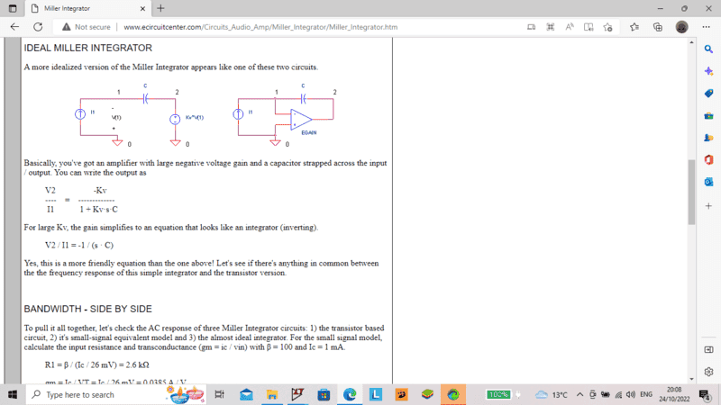
Screenshot of a webpage showing two circuit schematics of an idealized Miller integrator, each with a current source Ii, a capacitor C, and an amplifier with gain Kv, followed by the equations V2/Ii = -Kv / (1 + Kv·s·C) and V2/Ii = -1/(s·C).
 
Last edited by a moderator:
Can you write the equation for ##\frac{V_2}{I_I}## using the traditional differential equation for the current and voltage for a capacitor? Is it just the s-domain part that is confusing for you?
 
It's hard to know how to respond without knowing what part is confusing you or what your background knowledge in circuit analysis is. Try your nodal analysis and post it, then we'll know more about what to say.
 
It is not an "ideal" Miller integrator. This would only be the case (theoretically) for Kv approaching infinity.
 
it's how you get to the equation V2/II= -K/(1+KSC) where I'm confused.
Analysis gives II = V/R1 + (V1 - V2),S,C where V is the voltage over R1.
Also V2 = V1.K.
In order to get the right equation from the above I'd have to eliminate R1 which I cant.
 
ntetlow said:
(V1 - V2),S,C
What does this mean?

ntetlow said:
V is the voltage over R1.
Show us the circuit with RI (and all the other stuff).
 
attached is screenshot of the spice netlist for the schematics in the URL Under "ideal integrator" you will see RIN (sorry, I've called it R1). It is the resistance under the number 1 in the first screenshot that is not shown.
Screenshot of a SPICE netlist text page titled SPICE FILE, listing MILLER_INTEGRATOR.CIR with gain stage, small-signal and ideal integrator sections, plus model and analysis commands.
 
ntetlow said:
attached is screenshot of the spice netlist for the schematics in the URL Under "ideal integrator"
Can you switch to schematic view and take a screenshot of that? Thanks.
 
Attached is the ltspice schematic as per the netlist. I think it will be easier understanding if II is replaced by say SINE (0 1 1000).
LTspice schematic of an ideal Miller integrator: current source I1 drives a node with resistor R1 (1e12) to ground and capacitor C (500pf) feeding back to the output of voltage-controlled source E1 (gain 1000), with a PWL current source directive and .tran 3us.
 
ntetlow said:
I think it will be easier understanding if II is replaced by say SINE (0 1 1000).
OK thanks. Yes, or you can just leave it as an independent variable ##Il##.

Do you know about Thevenin/Norton transformations for sources yet? That would be my next step. But, if not, that's OK too.

So, this is just a network solution like the others you've done in the past. Define all of the stuff you need to make your node and loop equations (all of the currents and node voltages). Write them all down, loops of voltages for KVL, nodes with currents for KCL and show us that. After that you'll simplify/solve a set of equations.
 
The schematic you show in post #9 (your simulation) does not represent the schematic in post #1.

Please pay attention to the feedback polarity, one of them shows Positive feedback, the other shows Negative feedback.

Cheers,
Tom

p.s. A few decades ago, the standards changed for the position of the "+" and "-" inputs of op-amps, especially in simulation programs. The transition for us engineers was, shall we say, painful!
 
Attached is a screenshot showing my workings out so far. I cannot get the correct answer from these, however.
LTspice schematic of a feedback circuit with a series resistor R and a voltage source Vin, a capacitor C, a controlled source K driving Vout, and node V, plus typed equations: Vin - Vout = I(R + 1/S.C), Vin = I.R, Vout = V.K, (Vin - V)/R = (V - Vout).S.C = I.
 
Last edited by a moderator:
ntetlow said:
attached is a screenshot showing a schematic of an ideal miller integrator. Can anyone describe how the formula for V2/II is arrived at, can't work it out thru nodal analysis myself

Be skeptical of things you find online because they could be wrong

like this example http://www.ecircuitcenter.com/Circuits_Audio_Amp/Miller_Integrator/Miller_Integrator.htm

Two circuit schematics with the heading IDEAL MILLER INTEGRATOR: left, current source I1 into node 1, capacitor C to node 2, dependent source Kv*V(1) at node 2; right, the same with an op-amp gain block labelled EGAIN. Below are the equations V2/I1 = -Kv/(1 + Kv*s*C) and V2/I1 = -1/(s*C).

$$\text{If}~~~~\frac {V_2}{I}=\frac {-k}{1+ksc} ~~~~~~~~~~~\text{then}~~~V_2=-kI~~~~~~\text{when}~~c=0 $$

$$\text{But for this circuit, this conclusion is obviously not valid}$$
 
Last edited: