How to find the voltage threshold at which diode switches states?

AI Thread Summary
The discussion revolves around determining the voltage threshold at which a diode switches states in a circuit. The user has derived an equation using Kirchhoff's Voltage Law (KVL) but is struggling to find the diode current (i_D) necessary for calculating the load voltage (u_l). It is noted that when the diode is in the OFF state, the current is zero, allowing for the diode to be treated as an open circuit. The expected answer is -4.5V, which the user relates to the sum of voltage drops in the circuit. Clarification is sought on the relationship between the input voltage and the diode's state, particularly at the threshold of switching.
Andrei0408
Messages
50
Reaction score
8
Homework Statement
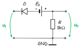
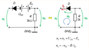
The diode in the figure is described by its offset model: U_D0=0.6V and r_d=0. Knowing that E_0=3.9V, find the voltage threshold u_l, at which the diode switches to its opposite state.
Relevant Equations
u_l=−u_D−i_D * R
I've attached pictures with the circuit and part of the attempted solution. I've replaced the diode with its offset model and obtained the equivalent circuit in the 2nd picture. After applying KVL, I've obtained that u_l=−u_D−i_D*R. Since U_D0 is greater than 0, I've deduced that the diode must be ON in this case, therefore u_D=0, so u_l=−i_D*R. The problem is I don't know how to find i_D so I can calculate u_l. The answer for this problem should be, according to the book, −4.5 . Any ideas? Thank you!
 

Attachments

  • Screenshot_13.png
    Screenshot_13.png
    7.5 KB · Views: 155
  • received_461045691428275.png
    received_461045691428275.png
    11.8 KB · Views: 159
Physics news on Phys.org
What is the diode current right at the threshold of switching? How does that effect your KVL equation?

So, let's say you started with a very negative input voltage, so you know the diode is conducting, what happens as you increase that input towards the switching threshold?
 
Well, when the diode switches to its OFF state, the current should be 0, U_D should be negative, so we could replace the diode with an open circuit, since there is no current
 
Andrei0408 said:
Well, when the diode switches to its OFF state, the current should be 0, U_D should be negative, so we could replace the diode with an open circuit, since there is no current
Yes, so how can you use that fact in the equations you created? What is KVL right at the threshold, when the current first reaches 0? What is the largest input voltage you can have and still have forward diode current (let's say 1uA)?
 
DaveE said:
Yes, so how can you use that fact in the equations you created? What is KVL right at the threshold, when the current first reaches 0? What is the largest input voltage you can have and still have forward diode current (let's say 1uA)?
Since the answer we're looking for should be -4.5V, I've observed that this could be -(0.6+3.9). So using this logic, u_D = E_0 and i_D * R = U_D0. Is this correct?
EDIT: I think I may have understood: if the diode is OFF then the input voltage is negative, which is why u_l = -U_D0 - E_0, please correct me if I'm wrong
 
Last edited:
Thread 'Minimum mass of a block'
Here we know that if block B is going to move up or just be at the verge of moving up ##Mg \sin \theta ## will act downwards and maximum static friction will act downwards ## \mu Mg \cos \theta ## Now what im confused by is how will we know " how quickly" block B reaches its maximum static friction value without any numbers, the suggested solution says that when block A is at its maximum extension, then block B will start to move up but with a certain set of values couldn't block A reach...
TL;DR Summary: Find Electric field due to charges between 2 parallel infinite planes using Gauss law at any point Here's the diagram. We have a uniform p (rho) density of charges between 2 infinite planes in the cartesian coordinates system. I used a cube of thickness a that spans from z=-a/2 to z=a/2 as a Gaussian surface, each side of the cube has area A. I know that the field depends only on z since there is translational invariance in x and y directions because the planes are...
Thread 'Calculation of Tensile Forces in Piston-Type Water-Lifting Devices at Elevated Locations'
Figure 1 Overall Structure Diagram Figure 2: Top view of the piston when it is cylindrical A circular opening is created at a height of 5 meters above the water surface. Inside this opening is a sleeve-type piston with a cross-sectional area of 1 square meter. The piston is pulled to the right at a constant speed. The pulling force is(Figure 2): F = ρshg = 1000 × 1 × 5 × 10 = 50,000 N. Figure 3: Modifying the structure to incorporate a fixed internal piston When I modify the piston...
Back
Top