_Bd_
- 107
- 0
Hi,
I'm building an experimental set-up for some heat exchanger I'm trying to analyze, I want to maximize the flow through this little piece.
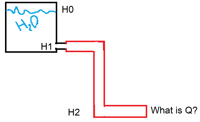
I have a stable temperature bath, (see picture) that has an evacuation valve on the bottom.
I only took introduction to Fluid Dynamics (found it amazing BTW). Anyways, I have a question as I always found this topics to be counter-intuitive and I just wanted to make sure.
If you look at the picture, and assuming some derived equations from Bernoulli's principle:
Volumetric flow rate is constant (right?)
Volumetric flow rate = velocity * Area of pipe
Velocity = Sqrt (2 * g * h)
My question is, on the drawing, the red pipe, does it help increase the flow rate or not?
Here's my line of reasoning:
- I would assume it DOES NOT, as the flow rate is limited by the orifice in which the water enters the piping system, so the max. flow rate I could ever get from this is the difference of H1 and H0 x the diameter of that orifice.
However, if say I took a point at H2 and tried to find out the velocity, in theory using the same equation I should have a higher velocity (differenc between H2 and H0) and therefore a higher flow rate? (this doesn't make sense in my opinion)
I just wanted some clarification on how to apply Bernoulli's principle in this particular case. As mentioned earlier I want to maximize the flow but I don't really know how to without using a submersible pump or something of the sort.NOTE: (There is a pump at the end that brings everything back to the top, so H0 remains constant)
I'm building an experimental set-up for some heat exchanger I'm trying to analyze, I want to maximize the flow through this little piece.
I have a stable temperature bath, (see picture) that has an evacuation valve on the bottom.
I only took introduction to Fluid Dynamics (found it amazing BTW). Anyways, I have a question as I always found this topics to be counter-intuitive and I just wanted to make sure.
If you look at the picture, and assuming some derived equations from Bernoulli's principle:
Volumetric flow rate is constant (right?)
Volumetric flow rate = velocity * Area of pipe
Velocity = Sqrt (2 * g * h)
My question is, on the drawing, the red pipe, does it help increase the flow rate or not?
Here's my line of reasoning:
- I would assume it DOES NOT, as the flow rate is limited by the orifice in which the water enters the piping system, so the max. flow rate I could ever get from this is the difference of H1 and H0 x the diameter of that orifice.
However, if say I took a point at H2 and tried to find out the velocity, in theory using the same equation I should have a higher velocity (differenc between H2 and H0) and therefore a higher flow rate? (this doesn't make sense in my opinion)
I just wanted some clarification on how to apply Bernoulli's principle in this particular case. As mentioned earlier I want to maximize the flow but I don't really know how to without using a submersible pump or something of the sort.NOTE: (There is a pump at the end that brings everything back to the top, so H0 remains constant)