saad87
- 83
- 0
Hello,
I'm considering using a logic-level MOSFET as a switch in a design. The drain of the MOSFET will be connected to an IC. The IC works at 3.3V and the maximum voltage at which it's guaranteed to read a low is just 0.8V.
Now, I think every MOSFET will able to satisfy this but I'm just trying to understand how can I tell? From looking at the datasheet of http://www.fairchildsemi.com/ds/FD%2FFDG6317NZ.pdf" , the drain current vs. V(DS) graph seems relevant.
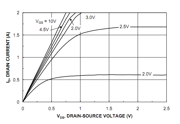
Let's assume I need a current of 500mA through the MOSFET. If I look at the above graph, it suggests that when Id = 500mA, the drain to source voltage should be around about 0.25V, for a gate voltage of 3V. Is my analysis correct?
I'm considering using a logic-level MOSFET as a switch in a design. The drain of the MOSFET will be connected to an IC. The IC works at 3.3V and the maximum voltage at which it's guaranteed to read a low is just 0.8V.
Now, I think every MOSFET will able to satisfy this but I'm just trying to understand how can I tell? From looking at the datasheet of http://www.fairchildsemi.com/ds/FD%2FFDG6317NZ.pdf" , the drain current vs. V(DS) graph seems relevant.
Let's assume I need a current of 500mA through the MOSFET. If I look at the above graph, it suggests that when Id = 500mA, the drain to source voltage should be around about 0.25V, for a gate voltage of 3V. Is my analysis correct?
Last edited by a moderator: