Pawllentiew
- 11
- 1
Thread moved from the technical forums, so no Homework Template is shown
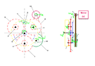
The discussion revolves around the kinematic analysis of a planetary gear mechanism, specifically focusing on the calculations needed to determine the transmission ratio, speed, and torque for a mechanism intended to drive a DC motor to a specific RPM for an LED application. The scope includes theoretical aspects of gear mechanisms, calculations for gear teeth, and practical applications involving weights and counterweights.
Participants express varying levels of understanding and approaches to the problem, with no consensus on the specific methods or formulas to apply. Multiple competing views on how to analyze the mechanism and the necessary calculations remain unresolved.
Participants highlight limitations in their understanding of the mechanism's design and calculations, including missing assumptions about gear dimensions and the need for specific formulas. The discussion reflects uncertainty about the application of theoretical concepts to the practical scenario presented.
Pawllentiew said:I looked at some tutorials and read the basic information to make a kinematic diagram. but all were based on a simple system with only 2-4 gears placed in series. I did not find an example to understand in which the ring gear rotates 3 planet gears. and how I could calculate that in the way they are placed in my example
That would be doing part of your homework for you, which we are not allowed to do. Post what you find, and we can use that as a place to start refining the discussion. Thank you @Master1022 for the helpful info.Pawllentiew said:I'll look over what you mentioned. thanks a lot. but if someone could make a quick sketch of what the kinematic diagram should look like it would help me tremendously
Please, see:Pawllentiew said:Can anyone help me with a kinematic analysis for the mechanism attached below? I need the outline of the mechanism, its notes and the necessary formulas to find out the transmission ratio and the rest of the values.
The output shaft must turn at 1600 RPM, but how much power is needed by the LED. What is the operating voltage and current of the LED ?Pawllentiew said:This mechanism aims to increase the rotation enough to rotate the dc motor at a speed high enough (1600 rpm) to turn on an LED.
I have the specifications of the product for which I am trying to recreate the mechanism. Gravity light 2Baluncore said:The output shaft must turn at 1600 RPM, but how much power is needed by the LED. What is the operating voltage and current of the LED ?
Then you can work your way backwards to the suspended mass, calculating the reducing speed and increasing torque through the system of gears.
Why? How did you calculate that? Or did you find it in a datasheet? (link?)Pawllentiew said:I think 0.1 W