Leverage and Forces on a Pivot System

Join the discussion
Ask a follow-up here, or get your own question answered by working scientists, mathematicians and engineers — people, not an autocomplete.
Real named experts · corrections over time · the nuance an AI answer skips
36 replies · 12K views
Saints-94
Messages
63
Reaction score
1
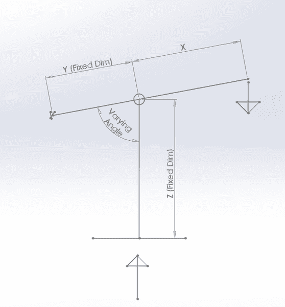
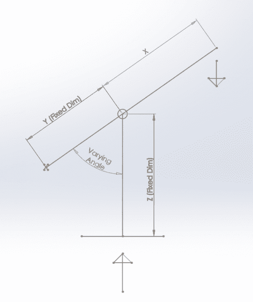
The diagram drawn below shows a lever system fixed to a point on the left with a pivot point (circle) on the line which attaches to vertical line. I have dimensions for Y and Z and the forces pulling the lever down on the right, and the force acting upwards from below. I am trying to work out the dimension for X to determine how long the lever needs to be to compress the upwards force, but I am unsure due to the varying angle as the lever is pulled down. Any help is greatly appreciated.
Forces Sketch.png

Before lever is pulled down.
upload_2017-2-21_16-13-3.png

After lever is pulled down.

Thanks.
 
Physics news on Phys.org
Hi Saints,

I sense some contradiction between the Y (FIxed Dim) and the Z piece seemingly staying vertical. Y is clearly shorter in the lower picture. Is the point where XY touches Z fixed on XY (and X also a 'Fixed Dim') or not ?
 
  • Like
Likes   Reactions: sophiecentaur
Y is a fixed dim (may not be to scale on the image). The point on the left of line Y is fixed, and the point where XY touches Z is fixed. However, X is a variable dim as I am trying to work out the length of leverage required to compress the force acting up.

I hope this clears it up a bit better.
Thanks.
 
Yes. The angle varies when the lever is pulled down, as Z always stays vertical. The circle represents a pivot point.
 
I understand the point moves in a circle, however, where Z touches XY it is a pivot point. The pivot allows Z to stay vertical as it moves around the red circle marked on.
 
Let me try again. In the left picture the arm is at 45 degrees, in the right it is horizontal. Do you see the distance between the left fixed point and the vertical Z has changed ? So either the leeft fixed point has moved to the left or Z has moved to the right and down.

upload_2017-2-22_15-40-10.png
 
I can see that the length of the arrows have changed as the lever moves down. However, the Y dimension has not changed- the length of the yellow line has stayed the same. From my understanding the pivot allows Z to stay at the same length and vertical, and also allows Y to stay at a fixed length?

upload_2017-2-22_14-49-0.png
 
The point on the left is always fixed.
 
Has anyone got any other suggestions as to how this would be solved? Thanks.
 
The problem as stated can only be solved for the case where the lever almost doesn't move . Applying down pressure on the lever end can then apply down force on the column without the point of contact moving significantly .
 
  • Like
Likes   Reactions: BvU
I'm struggling to work out what the equation would be. I want to find out the minimum length X would have to be to move the lever down, with a specified force pulling the lever down.
 
For what you describe - and assuming the small movement idea is ok - and if the 'variable angle' shown in your diagram is set to be somewhere near 90 degrees - the essential mechanism is just that of a simple lever .

Solution can be obtained by taking moments about the fixed pivot point at left end of lever .

Force down on column multiplied by distance Y = Force on end of lever multiplied by distance ( X + Y )

Example :

X = 2 metre , Y = 1 metre and force on end of lever = 100 N

Force on column * 1 = 100 * ( 2 +1 ) . Therefore force on column = 300 N
 
Thanks for your help.

However, the varying angle can be between 45 and 90 degrees. Does that have an affect on the force on the Z column? And also does the length of Z change the force created?
 
I am struggling now . Perhaps we have to define the mechanism more clearly .

When you say variable angle do you mean :

(a) that the lever has to swing through that angle when the force is applied ?
or
(b) that the lever could be preset to different angles but doesn't then swing significantly when force is applied ?
 
The column Z has to stay horizontal when the lever is pulled down. Therefore when the lever is up the angle will be aprrox. 45 degrees, and once its been pulled down it will end up at approx. 90 degrees.

The mechanism is waste compactor, similar to the one below.
41wF6gK1mQL._SX300_.jpg
 
  • Like
Likes   Reactions: BvU
So the vertical link is not actually fixed in position after all . Mystery solved .

For the lever being horizontal the calculation in #14 is still ok .

You could do a calculation for the lever at other angles but since the reaction force from squashing the waste is least when the lever is 45 deg up and greatest when it is somewhere near horizontal I think you could just use that one answer for horizontal for design purposes .

Any calculations are going to be approximate anyway due to the varying properties of waste material .
 
That's great. So as the force will be greatest at 90 degrees I can assume that it would be worst case?

Yes, they will be approximate. I have done some testing to get an approximate force required to compact household waste.
 
Okay, thanks. If I were to do a calculation for the lever when it is at 45 degrees, how would I incorporate the angle into the equation?
 
Saints-94 said:
That's great. So as the force will be greatest at 90 degrees I can assume that it would be worst case?
You should be careful here. The ratio of the two (parallel) vertical forces is the same for all angles of the arm - if the system really can be treated as implied in the diagrams at the top of the thread. So the Mechanical Advantage (or at least the Velocity Ratio) will be independent of angle.
 
sophiecentaur said:
You should be careful here. The ratio of the two (parallel) vertical forces is the same for all angles of the arm - if the system really can be treated as implied in the diagrams at the top of the thread. So the Mechanical Advantage (or at least the Velocity Ratio) will be independent of angle.

The two vertical forces will always be the same.

So does the angle need to be taken into consideration in the equation or not?
Thanks.
 
In practice there are two problems :

(a) Human operators tend to push or pull on long levers in a direction at right angles to the lever rather than just always straight downwards ,

(b) The drop link may swing from being vertical to an inclined position .

(a) and/or (b) can alter the calculated mechanical advantage figure considerably .

If working with all known quantities an exact calculation might be useful but in this case probably not worth the trouble .
 
(a)The lever will be pulled down from overhead, I can't see how that will affect the calculation? (b)Also I am making an assumption that the 'drop link' will stay vertical for the purpose of the equation.

Going back to the formula discussed previously, is there a way to incorporate the change in the 'varying angle', or is it not necessary?
 
Saints-94 said:
(a)The lever will be pulled down from overhead, I can't see how that will affect the calculation? (b)Also I am making an assumption that the 'drop link' will stay vertical for the purpose of the equation.
Going back to the formula discussed previously, is there a way to incorporate the change in the 'varying angle', or is it not necessary?
Have you done any reading around levers and moments? The principle of moments uses the phrase 'perpendicular distance' in the definition of the moment of a force around a fulcrum. This link gives you a way into the topic if you haven't already read about it. The simple, lower school, treatment of moments is only restricted to horizontal levers / see-saws etc. but the angle is important if you want to understand it more fully.
 
I have done some work on moments previously.

I understand that when the line is at 90 degrees: Force on the vertical line multiplied by Y = Force on end of lever multiplied by ( X + Y )

However, when the lever is at 45 degrees I am struggling to create a formula that incorporates the angle.
 
Sorry, maybe 'create' was the wrong terminology.

I am trying to write out the formula that incorporates the angle.

For the two instances - line at 45 and 90 degrees- I have written the formulas below.

When the line is at 90 degrees: Force on the vertical line multiplied by Y = Force on end of lever multiplied by ( X + Y )

When the line is at 45 degrees: Force on the vertical line (sin45) multiplied by Y = Force on end of lever multiplied by ( X + Y )

Are these correct?
 
Nidum said:
Human operators tend to push or pull on long levers in a direction at right angles to the lever rather than just always straight downwards
For good reasons: the handlebar is also constrained to move along an arc with radius X+Y. I don't think a component along the X Y arm is doing anything useful -- anyone ?

So I drew ##F_1## as Nidum suggests

Moment balance: $$F_1 \times (X+Y) = F_2 \times X$$

Decomposition of ##F_2##: $$F_{2,\rm v} = F_2 \sin 45^\circ$$

So your formula should be $$F_{2,\rm v} = F_1 {X+Y\over X} \sin 45^\circ$$

Again, if Z starts moving, the top is constrained to move along the dashed arc, but that shouldn't be a big issue: let go, press again is the recipe.

I do see trouble for big strong guys: they can easily compress the stuff so tightly that it doesn't come out any more when the bin is collected...

upload_2017-2-24_22-51-5.png
 
  • Like
Likes   Reactions: Nidum