Motor driven pendulum - How to track its position?

In summary, the conversation discusses a test pendulum used for rock wool production, driven by two induction motors. The position and speed of the motors at any given time are known, but the movement of the pendulum is currently plotted using a simple analog procedure. The question is how to describe the movement with equations to make it easier to analyze. A suggested solution is to write a program using initial positions and outputs of position and acceleration. It is also recommended to plot the entire linkage at each step for visual confirmation and debugging. Octave is suggested as a free alternative to Matlab for this application.
  • #1
maxitaxi
1
0
Hello,

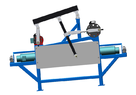
On the image below is a test pendelum for rock wool production. The pendelum is driven by two induction motors. When the right motor makes one revolution, the left motor makes two revolutions. The motors are positionally locked (example: when the right motor is at 35.3° the left motor is at 70.6°). The above part works OK.
1659337212629.png

Currently we are using a simple analog procedure (marker and whiteboard) to plot the position of the pendelum (shown on the image below).

1659337667141.png

On the image below are the mesurements of the moving parts [mm]. The position of both motors at any given time is known. The speed at any given time is also known (nominal speed is 1500 rpm).
IMG_20220801_091750.jpg


My question is how can movement of this sort of pendelum (where the marker is located) be described with equations. It would be a lot more transparent and easier to analyze to have the pendelum moevement data in digital form.

Thank you for your answer in advance.

Regards.
 

Attachments

  • 1659337116351.png
    1659337116351.png
    13.2 KB · Views: 72
Physics news on Phys.org
  • #2
I once had a similar problem. It was to design a four bar linkage to follow a specific motion profile while minimizing peak acceleration. I wrote a program in Matlab with initial positions as inputs, and plots of position and acceleration as functions of input shaft position as outputs.

You have more links, but exactly one input (the second motor is geared to the first motor), and one output. It should be an easy program to write:

Start with the motor on the left.
Calculate position of motor crankpin.
Calculate position of pin between connecting rod and the top beam.
Calculate position of pin in middle of top beam.
Calculate position of crankpin of motor on the right.
Calculate position of pin connecting second motor connecting rod with pendulum.
Calculate position of end of pendulum.
Plot position of pendulum for one revolution of the slower motor.
(Optional) You can use numerical differentiation to calculate velocity and acceleration of the pendulum or any other point in the system.

Hint: It is good practice to plot the entire linkage at each step in the simulation. It slows the simulation down, but you get visual confirmation that the simulation is working properly. It is also helpful for debugging. And it's an excellent tool for showing other people how the mechanism works.

If you do not have Matlab, Octave (https://octave.org/) is Matlab compatible freeware. It's not quite as good as Matlab, but more than good enough for your application.
 
  • Like
Likes hutchphd

1. How does a motor driven pendulum work?

A motor driven pendulum consists of a pendulum attached to a motor, which provides energy to keep the pendulum in motion. The motor is usually controlled by a circuit that regulates the frequency and amplitude of the pendulum's oscillations.

2. How do you track the position of a motor driven pendulum?

The position of a motor driven pendulum can be tracked by using sensors such as optical encoders or potentiometers. These sensors measure the angle of the pendulum and send the data to a microcontroller, which can then calculate the position of the pendulum.

3. What factors affect the accuracy of tracking the position of a motor driven pendulum?

The accuracy of tracking the position of a motor driven pendulum can be affected by factors such as the quality of the sensors, the precision of the motor, and any external disturbances that may affect the pendulum's motion.

4. How can you improve the accuracy of tracking the position of a motor driven pendulum?

To improve the accuracy of tracking the position of a motor driven pendulum, you can use high-quality sensors, calibrate the system regularly, and minimize external disturbances. Additionally, using a more precise motor and optimizing the control circuit can also help improve accuracy.

5. What are some real-world applications of motor driven pendulums?

Motor driven pendulums have various applications, including timekeeping devices such as clocks and metronomes, motion control systems in robotics, and energy harvesting systems. They can also be used in scientific experiments to study oscillatory motion and demonstrate concepts of energy transfer and conservation.

Similar threads

  • Engineering and Comp Sci Homework Help
Replies
4
Views
2K
  • Programming and Computer Science
Replies
1
Views
1K
  • Engineering and Comp Sci Homework Help
Replies
7
Views
2K
  • Introductory Physics Homework Help
Replies
9
Views
701
Replies
10
Views
4K
  • Other Physics Topics
Replies
0
Views
4K
  • Aerospace Engineering
Replies
2
Views
7K
  • Introductory Physics Homework Help
Replies
2
Views
4K
  • Electromagnetism
2
Replies
49
Views
9K
Back
Top