Motor Sizing for Wheel Endurance Testing

AI Thread Summary
In a wheel endurance testing application, the motor sizing is crucial for effectively rotating a drum while applying force to various wheel sizes. The torque calculation should consider the radius of the drum if the motor is mounted on it, but the wheel's radius if the motor is attached to the wheel. The force applied by the wheel can lead to significant torque values, necessitating careful consideration of frictional forces from both the bearings and the deformed wheel. A variable velocity connection, such as a pulley-belt system or a variable frequency drive, is recommended to accommodate different wheel diameters and specified angular velocities. Proper torque calculations and motor sizing are essential for accurate testing results.
SR71
Messages
1
Reaction score
0
TL;DR Summary
Motor sizing for wheel endurance testing
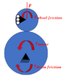
I am working with a wheel endurance testing application. I am trying to size a motor for the system. Basically, I have a drum which has to be rotated by the motor. I have different size wheels that I have to test. The motor is supposed to rotate the drum and then the wheel is pushed onto the drum with a force.

My question is when I want to find the torque (Fx perpendicular distance) do I use the radius of the drum or the radius of the wheel being tested? Currently, I am using the radius of the drum as the wheel is being pushed onto the drum but this gives me huge numbers as the wheel is pushing with 1000-2500 lbs of force.

Thank you in advance.

Link:
Wheel Endurance FBD.png
 
Last edited by a moderator:
Engineering news on Phys.org
If the motor is on the drum then use the drum radius. If it is on the wheel then use the wheel radius.

Torque will be different in both cases but so will be the angular velocity. In both cases, the power will always be the same.
 
SR71 said:
My question is when I want to find the torque (Fx perpendicular distance) do I use the radius of the drum or the radius of the wheel being tested? Currently, I am using the radius of the drum as the wheel is being pushed onto the drum but this gives me huge numbers as the wheel is pushing with 1000-2500 lbs of force.
How is the radius of the drum or wheel relevant for this? The force is aligned with the axles so it's got no leverage. Am I misunderstanding the drawing? Or are you obtaining the tangential component due to the friction?

Since the angular velocity is constant during the test (or so I think from the video), I would say to size the motor you just need it to have enough torque to overcome the friction from the bearings and the friction due to the deformed wheel rolling.
I guess the second one should be the greatest one but I don't know how to derive it yet.
 

Attachments

  • 1690647772315.png
    1690647772315.png
    14 KB · Views: 122
  • Like
Likes Juanda and Lnewqban
Welcome, @SR71 !

Due to the different diameters of wheels to be tested, I recommend to engineer a variable velocity connection between motor and drum.
It could be a variable pulley-belt system, or a VFD (variable frequency drive), for example.
I assume each test has one or several specified angular velocities for the wheel.
 
  • Like
Likes Juanda and Tom.G
Thread 'Physics of Stretch: What pressure does a band apply on a cylinder?'
Scenario 1 (figure 1) A continuous loop of elastic material is stretched around two metal bars. The top bar is attached to a load cell that reads force. The lower bar can be moved downwards to stretch the elastic material. The lower bar is moved downwards until the two bars are 1190mm apart, stretching the elastic material. The bars are 5mm thick, so the total internal loop length is 1200mm (1190mm + 5mm + 5mm). At this level of stretch, the load cell reads 45N tensile force. Key numbers...
After over 25 years of engineering, designing and analyzing bolted joints, I just learned this little fact. According to ASME B1.2, Gages and Gaging for Unified Inch Screw Threads: "The no-go gage should not pass over more than three complete turns when inserted into the internal thread of the product. " 3 turns seems like way to much. I have some really critical nuts that are of standard geometry (5/8"-11 UNC 3B) and have about 4.5 threads when you account for the chamfers on either...
Back
Top