nikodean1
Hi everyone, i'd like to share my packaged (plug and play) solar system project that I assembled at home. I used mostly standard parts such as a charge controller, inverter, 12 Volt UPS battery, and a pair of NEMA 5-15 R power outlets.
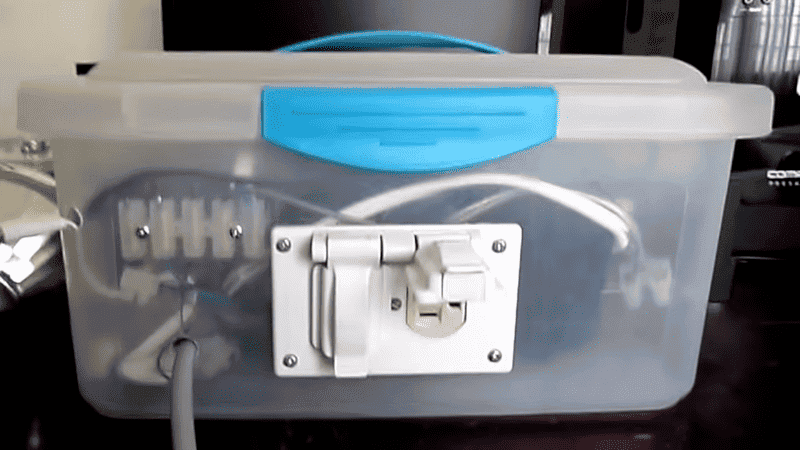
I built the automatic transfer switch and battery overload protector using a microcontroller, BJT, and relay.
I initially built it years ago, but recently incorporated the transfer switch to make it more 'plug and play', so to speak.
The end goal of this ongoing project is to discover the cheapest and quickest ways to implement solar systems (i.e. reducing the amount of labour required during installation), and also to encourage anyone that views it to pursue a similar goal/improve it as much as possible.
It looks slightly different now, as it has USB charging outlets (1 is 2.1 amps and the other is 1 amp), but those outlets are my first step towards my goal of powering more devices with DC (without the use of the inverter). I hope to develop a universal 12 + 5 + 3.3 VDC output that devices such as computers and TVs can use (I have a radical goal of a solar and wind-powered world without wall warts and big, heavy, expensive 120 Volt PSUs).
Here's the project description with further details, as well as a video demonstrating it's operation: https://www.kompulsa.com/2017/02/14/look-plug-play-solar-system-project/
Thank you for reading!
I built the automatic transfer switch and battery overload protector using a microcontroller, BJT, and relay.
I initially built it years ago, but recently incorporated the transfer switch to make it more 'plug and play', so to speak.
The end goal of this ongoing project is to discover the cheapest and quickest ways to implement solar systems (i.e. reducing the amount of labour required during installation), and also to encourage anyone that views it to pursue a similar goal/improve it as much as possible.
It looks slightly different now, as it has USB charging outlets (1 is 2.1 amps and the other is 1 amp), but those outlets are my first step towards my goal of powering more devices with DC (without the use of the inverter). I hope to develop a universal 12 + 5 + 3.3 VDC output that devices such as computers and TVs can use (I have a radical goal of a solar and wind-powered world without wall warts and big, heavy, expensive 120 Volt PSUs).
Here's the project description with further details, as well as a video demonstrating it's operation: https://www.kompulsa.com/2017/02/14/look-plug-play-solar-system-project/
Thank you for reading!
Attachments

