Aeroflux
- 3
- 2
- TL;DR
- Simulating a railgun in Matlab with simple numerical methods, with a hypothetical 500V 30mF capacitor and a 5mm wide square projectile, and it barely accelerated at all.
[CODE lang="matlab" title="RG_numerical_sim" highlight="14-25,43,48,49"]clear
clc
u0= 4*pi*1e-7 %magnetic permittivity constant
%simulation settings
n=1000;
v=zeros(1,1000);
t = linspace(0,0.1,n);
%railgun electrical properties
R_wire = 0.1; %0.1 ohms of wire
R_projectile = 2e-6;
R_t = R_wire+R_projectile;
V_cap = zeros(1,n);
V_cap(1) = 500; % capacitor maximum voltage
C_cap = 0.03; % Capacitance in farads
SR_rail = 2*2.488e-4; %specific resistance of rails
%Railgun setup
d=0.005; %rail separation
w=d; %projectile width
r=d/sqrt(2); %projectile radius
m=0.005; %mass in kg
u_s = 0.53; %friction factor between copper and steel
l_rail = 0.5; %length of rail
v(1) = 5; %initial velocity
B0=0; %magnetic field from permenant magnet
s=zeros(1,n); %updated, displacement from initial position
I=zeros(1,n); %current over time
B=zeros(1,n); %magnetic field from rails
a=zeros(1,n); %acceleration
F=zeros(1,n); %magnetic force
warning=0;
for i=1:n
if(s(i)<=l_rail) %rail length of 0.5m
%capacitor discharge
dt=t(2)-t(1);
q=V_cap(i)*C_cap;
R=R_t+SR_rail*s(i);
I(i)=V_cap(i)/R;
dq=-I(i)*dt;
V_cap(i+1) = (q+dq)/C_cap;
%calculate magnetic force
B(i)=B0+abs((u0*I(i))/(2*pi*d)*log((d-r)/r));
friction=m*u_s*10;
F(i)=I(i)*B(i)*w;
if(F(i)<=friction && warning ==0)
disp('Warning: magnetic force unable to overcome friction')
warning = 1;
end
a(i)=(F(i)-friction)/m;
v(i+1) = v(i)+a(i)*dt;
s(i+1) = s(i)+v(i)*dt;
else
v(i+1) = v(i);
V_cap(i+1) = V_cap(i);
s(i+1) = s(i)+v(i)*dt;
end
end
if(s(end)>l_rail)
fprintf('muzzle velocity of %d m/s',v(end))
end
E_cap=0.5*C_cap*(V_cap(1)^2-V_cap(end)^2);
KE_gain=0.5*m*(v(end)^2-v(1)^2);
fprintf('Energy discharged by capacitors: %d Joules\n',E_cap)
fprintf('Kinetic Energy gained by projectile: %d Joules\n', KE_gain)
efficiency = KE_gain/E_cap
tiledlayout(2,2)
nexttile
plot(t,V_cap(1:1000)./R);
xlabel('time(s)')
ylabel('Current(A)')
nexttile
plot(t,B(1:1000));
xlabel('time(s)');
ylabel('Magnetic field (T)');
nexttile
plot(s,V_cap./R)
xlabel('distance along rail (m)')
ylabel('Current(A)')
nexttile
plot(t,v(1:1000))
xlabel('time(s)')
ylabel('velocity(m/s)')[/CODE]
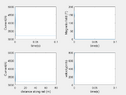
Since my first class in electromagnetism, I have been fascinated by the simple yet powerful railguns. But since building one can be expensive and potentially dangerous, I've opted to simulate one in Matlab for now. I've studied electromagetism in the first year of physics, and I have attempted to derive a formula about the forces on a square railgun projectile, but is confused on whether the projectile's thickness or length have any affect. So I decided to use the formula on this site for my calculations.

The basic design (cross section) looks something like this. 2 rectangular copper rails placed 3mm apart, with grooves for the projectile to sit on and maintain electrical contact. The rails would be 0.5m long. The projectile itself would be a square prism 5mm on its side, and assume it weighs 10 grams. The capacitor banks would be 3x 500V 10mF electrolytic capacitors. I made an assumption of the wires having 0.1 ohms, and add it up with the resistance of the rails and projectile. In addition, the projectile will have an initial velocity of 5m/s from a spring that pushes it into the barrel. I also searched up that copper and steel has a friction factor of 0.53. Let the simulation begin:

Oh no! It appears that the capacitors gets drained within 10 milliseconds, accelerating the projectile by a measly 1.3m before it starts slowing down due to friction. So the capacitors is going to dump like 3750J of energy into the system, sent sparks flying, only to deliver less impact than a nerf dart. Running the code again with different values, it would take like 4200 volts to accelerate the projectile to 100m/s, 12kV to break the sound barrier (the air between the rails would break down first).
I will attach my code below if anyone is interested in trying it out, and bonus for pointing out any mistakes I made. But if it was correct, should I blame it on the magnetic permittivity being only 1.2*10^-6, give up my fantasies about having a railgun, and start daydreaming about coilguns instead?
clc
u0= 4*pi*1e-7 %magnetic permittivity constant
%simulation settings
n=1000;
v=zeros(1,1000);
t = linspace(0,0.1,n);
%railgun electrical properties
R_wire = 0.1; %0.1 ohms of wire
R_projectile = 2e-6;
R_t = R_wire+R_projectile;
V_cap = zeros(1,n);
V_cap(1) = 500; % capacitor maximum voltage
C_cap = 0.03; % Capacitance in farads
SR_rail = 2*2.488e-4; %specific resistance of rails
%Railgun setup
d=0.005; %rail separation
w=d; %projectile width
r=d/sqrt(2); %projectile radius
m=0.005; %mass in kg
u_s = 0.53; %friction factor between copper and steel
l_rail = 0.5; %length of rail
v(1) = 5; %initial velocity
B0=0; %magnetic field from permenant magnet
s=zeros(1,n); %updated, displacement from initial position
I=zeros(1,n); %current over time
B=zeros(1,n); %magnetic field from rails
a=zeros(1,n); %acceleration
F=zeros(1,n); %magnetic force
warning=0;
for i=1:n
if(s(i)<=l_rail) %rail length of 0.5m
%capacitor discharge
dt=t(2)-t(1);
q=V_cap(i)*C_cap;
R=R_t+SR_rail*s(i);
I(i)=V_cap(i)/R;
dq=-I(i)*dt;
V_cap(i+1) = (q+dq)/C_cap;
%calculate magnetic force
B(i)=B0+abs((u0*I(i))/(2*pi*d)*log((d-r)/r));
friction=m*u_s*10;
F(i)=I(i)*B(i)*w;
if(F(i)<=friction && warning ==0)
disp('Warning: magnetic force unable to overcome friction')
warning = 1;
end
a(i)=(F(i)-friction)/m;
v(i+1) = v(i)+a(i)*dt;
s(i+1) = s(i)+v(i)*dt;
else
v(i+1) = v(i);
V_cap(i+1) = V_cap(i);
s(i+1) = s(i)+v(i)*dt;
end
end
if(s(end)>l_rail)
fprintf('muzzle velocity of %d m/s',v(end))
end
E_cap=0.5*C_cap*(V_cap(1)^2-V_cap(end)^2);
KE_gain=0.5*m*(v(end)^2-v(1)^2);
fprintf('Energy discharged by capacitors: %d Joules\n',E_cap)
fprintf('Kinetic Energy gained by projectile: %d Joules\n', KE_gain)
efficiency = KE_gain/E_cap
tiledlayout(2,2)
nexttile
plot(t,V_cap(1:1000)./R);
xlabel('time(s)')
ylabel('Current(A)')
nexttile
plot(t,B(1:1000));
xlabel('time(s)');
ylabel('Magnetic field (T)');
nexttile
plot(s,V_cap./R)
xlabel('distance along rail (m)')
ylabel('Current(A)')
nexttile
plot(t,v(1:1000))
xlabel('time(s)')
ylabel('velocity(m/s)')[/CODE]
Since my first class in electromagnetism, I have been fascinated by the simple yet powerful railguns. But since building one can be expensive and potentially dangerous, I've opted to simulate one in Matlab for now. I've studied electromagetism in the first year of physics, and I have attempted to derive a formula about the forces on a square railgun projectile, but is confused on whether the projectile's thickness or length have any affect. So I decided to use the formula on this site for my calculations.
The basic design (cross section) looks something like this. 2 rectangular copper rails placed 3mm apart, with grooves for the projectile to sit on and maintain electrical contact. The rails would be 0.5m long. The projectile itself would be a square prism 5mm on its side, and assume it weighs 10 grams. The capacitor banks would be 3x 500V 10mF electrolytic capacitors. I made an assumption of the wires having 0.1 ohms, and add it up with the resistance of the rails and projectile. In addition, the projectile will have an initial velocity of 5m/s from a spring that pushes it into the barrel. I also searched up that copper and steel has a friction factor of 0.53. Let the simulation begin:
Oh no! It appears that the capacitors gets drained within 10 milliseconds, accelerating the projectile by a measly 1.3m before it starts slowing down due to friction. So the capacitors is going to dump like 3750J of energy into the system, sent sparks flying, only to deliver less impact than a nerf dart. Running the code again with different values, it would take like 4200 volts to accelerate the projectile to 100m/s, 12kV to break the sound barrier (the air between the rails would break down first).
I will attach my code below if anyone is interested in trying it out, and bonus for pointing out any mistakes I made. But if it was correct, should I blame it on the magnetic permittivity being only 1.2*10^-6, give up my fantasies about having a railgun, and start daydreaming about coilguns instead?