Optimetrics simulation of a coil and moving permanent magnet in Ansys Maxwell

In summary: The frictional heating of the PM guides only needs to be less than the electrical energy generated to exceed 50% efficiency....
  • #1
Y_G
9
5
I'm trying to simulate a Magnetostatic problem. In my model there are two coils and a reciprocating permanent magnet. I defined a parameter, Xpm (movement of permanent magnet) in x direction to imply the reciprocating movement of permanent magnet like a piston. Xpm = f(t). I defined "t" as sweep parameter. When the time changes and the magnet moves back and forth, the amount of Flux will change in the iron core of the coil. Obviously, because of magnetostatic simulation, I can't obtain induced current in coils.
Is it possible to obtain how much voltage induced in coils by moving the magnet?

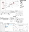
The picture I attached shows how I setup the model. After calculation of "MagFlux" in Optimetrics section, I used excel to calculate how much voltage induced to the coil by using this equation: V = -d(phi)/dt.

Is that correct what I've done?
 

Attachments

  • Sliding-Generator.jpg
    Sliding-Generator.jpg
    43.6 KB · Views: 155
Engineering news on Phys.org
  • #2
Y_G said:
Is it possible to obtain how much voltage induced in coils by moving the magnet?
Welcome to PF.
Yes. How many turns of wire are wound on each coil ?
 
  • #3
Thank You, 2000 turns for each coil. I did this modeling in two ways. 2000 and 1000 turns. In the first case, the amount of magnetic flux obtained was higher. To calculate the induced current in the coil, assuming the AWG24 wire, I calculated the length of the coil and obtained its resistance. Finally, the induced current was obtained with the relation V = RI.
 
  • #4
Should the coil be modeled as a closed circuit, with current and partial magnetic cancellation, or should you model it open circuit for voltage?
That will depend on whether you are generating power or measuring magnet position and velocity. Why are you doing this design?
 
  • #5
This is a kind of generator, If we could say. Sliding Generator. So I think, It should be modeled open circuit for voltage. Actually I defined another parameter for calculating force on moving magnet in x-direction. But I'm aware because of magnetostatic simulation the force may different from real case scenario.
I hope I understand what you mean.
 
  • #6
Y_G said:
This is a kind of generator, If we could say. Sliding Generator. So I think, It should be modeled open circuit for voltage.
That's contradictory. A generator does not generate open circuit.
 
  • #7
anorlunda said:
That's contradictory. A generator does not generate open circuit.
Thanks for replying. I only defined stranded coils with terminals. I don't know if it could be a open circuit or close circuit.
 
  • #8
So are you just experimenting to see what you can do?

If so, I suggest starting open circuit, and measuring what voltage you get. Maybe you can see how the voltage varies as the magnet makes a complete revolution.
 
  • Like
Likes Y_G
  • #9
This is fundamentally an inefficient generator topology because the magnetic field through the coils does not change polarity.

The PM flux is divided into two paths. The difference between maximum and minimum flux comes from the series length of the sides that are part of the two magnetic circuits through the coils. Is it possible to increase the flux change, and so the output, by reducing the mass of magnetic material in the side rails.

The cost will be high because;
1. The PM must slide between the rails with a minimum gap.
2. There are two coils.
 
  • Like
Likes Y_G
  • #10
anorlunda said:
So are you just experimenting to see what you can do?

If so, I suggest starting open circuit, and measuring what voltage you get. Maybe you can see how the voltage varies as the magnet makes a complete revolution.
Thanks
 
  • #11
Baluncore said:
This is fundamentally an inefficient generator topology because the magnetic field through the coils does not change polarity.

The PM flux is divided into two paths. The difference between maximum and minimum flux comes from the series length of the sides that are part of the two magnetic circuits through the coils. Is it possible to increase the flux change, and so the output, by reducing the mass of magnetic material in the side rails.

The cost will be high because;
1. The PM must slide between the rails with a minimum gap.
2. There are two coils.
Thank you so much for your help. Despite of ordinary generator, maybe it could be possible to omit the gap between rails and PM. Also I'm curious about reducing the force on PM. If the force is reduced to a minimum level the efficiency of the generator will increase significantly.
 
  • #12
Y_G said:
Also I'm curious about reducing the force on PM. If the force is reduced to a minimum level the efficiency of the generator will increase significantly.
There should be no force on the PM if the coils are open circuit.

The integral of (force * distance) of the PM, will equal the electrical energy generated, plus the heating due to friction. The frictional heating of the PM guides only needs to be less than the electrical energy generated to exceed 50% efficiency. Hopefully, there will be a high force on the PM because it is converting significant mechanical energy into electrical energy. The geometry of this generator makes that unlikely.

Maybe you could connect the coils in series opposition so the output is symmetrical AC. But then you still have asymmetric magnetisation of the magnetic circuit by the PM.
 
  • Like
Likes Y_G
  • #13
Thank you, in another simulation I want to apply I(t) (current of coils) , corresponding to voltage calculated in previous simulation. I hope that corrects the force exerted on PM somehow. I'll share here the results.
 

1. What is Optimetrics simulation in Ansys Maxwell?

Optimetrics simulation in Ansys Maxwell is a process of optimizing the design of a coil and moving permanent magnet in order to achieve the desired performance. It involves using the software's optimization tools to adjust various parameters and analyze the results to find the best design.

2. How does the coil and permanent magnet interact in Ansys Maxwell?

In Ansys Maxwell, the coil and permanent magnet interact through the magnetic fields they produce. The coil produces a magnetic field when a current is passed through it, while the permanent magnet produces a constant magnetic field. The interaction between these fields causes the permanent magnet to move in relation to the coil.

3. What are the main benefits of using Ansys Maxwell for Optimetrics simulation?

Ansys Maxwell offers a variety of benefits for Optimetrics simulation, including accurate and efficient analysis, a user-friendly interface, and the ability to handle complex designs. It also allows for easy optimization and customization of parameters, resulting in improved design performance.

4. What are some key parameters to consider when conducting Optimetrics simulation in Ansys Maxwell?

Some key parameters to consider when conducting Optimetrics simulation in Ansys Maxwell include the geometry and material properties of the coil and permanent magnet, as well as the current and velocity of the moving magnet. Other factors such as the environment and external forces may also need to be taken into account.

5. Can Ansys Maxwell simulate other types of electromagnetic devices?

Yes, Ansys Maxwell can simulate a wide range of electromagnetic devices, including motors, generators, transformers, and sensors. It has the capability to handle various types of electromagnetic phenomena, making it a versatile tool for designing and optimizing different devices.

Similar threads

  • Electrical Engineering
Replies
3
Views
525
  • Electrical Engineering
Replies
1
Views
994
  • Electrical Engineering
Replies
1
Views
780
  • Electrical Engineering
Replies
7
Views
2K
  • Electrical Engineering
Replies
10
Views
2K
Replies
1
Views
671
Replies
4
Views
1K
Replies
5
Views
7K
Replies
1
Views
709
Replies
2
Views
2K
Back
Top