Misc. Problem generating spark under water for cavitation bubbles

AI Thread Summary
Experiments with cavitation bubbles using a high voltage generator coil have faced challenges in generating consistent sparks underwater. The setup involves copper enameled wire electrodes with a gap of less than 1mm, powered by a pulse generator coil capable of producing around 1000kV. Initial attempts to create sparks have been hindered by issues such as electrode contamination from copper salts, which may short-circuit the voltage, and the limited energy output of the device, leading to continuous electrolysis instead of sparking. Suggestions for improvement include using carbon rods or platinum tips for electrodes, ensuring clean and dry connections to reduce leakage, and potentially using a more powerful voltage source with faster rise times. The importance of measuring voltage and understanding energy requirements for bubble generation is emphasized, as well as the need for safety precautions when working with high voltage. Recent experiments have shown some success by introducing an air gap in the setup, allowing for spark generation underwater, although further tuning and adjustments are needed for optimal performance.
Beekeeper
Messages
14
Reaction score
2
TL;DR Summary
I cannot consistently generate a spark under water using a High Voltage Generator coil. Can you help explain why?
Hi,

I am trying to do some experiments with cavitation bubbles by generating a spark under water however I am having some trouble and was wondering if anyone would be able to help or offer some advice.

The problem I am having is I cannot generate the spark consistently. I place the electrodes in (distilled) water, apply the high voltage across them, they will usually spark a few times and then stop and fail to spark again after that.

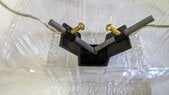
The setup I am using is described in the following (attached) diagram:
1736248947904.png

The electrodes are just copper enameled wire with a gap < 1mm. I am using a small "High Voltage Generator Pulse Generator Coil" (goes by other names see this link) of around 1000kV to generate the high voltage across the electrodes. I am controlling a "High Voltage Pulse Generator Coil" with a trigger switch and an Arduino to precisely set the time for the spark. The electrodes themselves are placed in distilled water rather than tap water to avoid potential electrolysis.

Things I have tried:
- different spark durations from 50ms to 2000ms most have similar results
- different thickness of electrode wire from 0.1 to 0.85mm
- multiple strands of electrode wire 3 x 0.25mm and 2 x 0.63mm
- different quality distilled water (currently settled on high grade conductivity <= 1uS/cm)
- different coils, I also tried a 400kV coil with similar results

Although I have not read or seen anyone generate a spark with this "High Voltage Pulse Generator Coil" I thought it would be possible based on this paper which generated a spark using a small piezo electric igniter. But even so I am not sure if using the "High Voltage Pulse Generator Coil" is the problem so curious to hear thoughts on that.

I could try another circuit or setup, but was hoping to first get some advice and try to understand the problem first.

Thanks for taking the time to read my post.
 
Physics news on Phys.org
I would guess that after the first few sparks, your "distilled water" will be clouded by copper salts from your electrode. I would also guess that those copper salts are shorting your voltage.

You'll likely have this same problem with almost any electrode material. But I would try carbon rods.
 
Ok thanks! Sounds plauseable and thanks for the suggestion to use carbon rods instead. I will give that a try.
 
.Scott said:
I would try carbon rods.
Or platinum tips?
 
Beekeeper said:
TL;DR Summary: I cannot consistently generate a spark under water using a High Voltage Generator coil. Can you help explain why?

Although I have not read or seen anyone generate a spark with this "High Voltage Pulse Generator Coil" I
Is this a joke or a spoof? I looked at the spec on Amazon and it seems to claim hundreds of kV and 5A output (nearly a Megawatt!!). It's reasonable to suppose this gizmo can make sparks for gas cooker ignition etc but that little box with thin wires coming out of it really doesn't look the part. Look at the care with which an old CRT in a colour tv manages to cope with very high volts.

Have you any way of measuring what your box actually produces? Good fun if you are careful of secondary accidents when the spark hits you and makes you jump.
 
Teflon insulating film has a breakdown voltage of 60 to 173 Mv/m. So 700Kv would likely damage that insulation. But the product comes with warnings that it will be damaged if the maximum air gap is exceeded.

The specified maximum air gap is 1.5cm which corresponds to 45Kv. So, you're right, that's a very theoretical 700Kv.

As far as the megawatt, it's only a megawatt during the pulse - and they do not specify the pulse width.

I also noticed that they show 9 views of this device. And 9 out of 9 are side views. We never get to see what either end looks like. A good look at the high voltage end would have provided more clues about the practical maximum output voltage.
 
That thing is a high voltage coil driven by a pulse generator. The output of the coil is charging a capacitor through some diodes. When the voltage goes high enough and breaks down the insulation a spark is generated, discharging the capacitor. Then, all over again, few dozen times a second or more.
Weaker insulation means more frequent sparks at lower voltage.
If there is a constant load it may counter the charging pulses and prevent sparks to happen.
So actually the change in the water is a good explanation.
You may try to introduce some currents to the pool to disperse the salts.

Beekeeper said:
different spark durations from 50ms to 2000ms
What you set there is the number of sparks in a batch. If you want single spark with adjustable duration/energy then you need an entirely different setup.
 
Last edited:
Wow, thanks for all your replies! I been busy last few days so I did not expect all these responses when I got back to this so thanks.

I found some carbon rods on ebay, so hope to test in a day or so. In the meantime I tried out some graphite rods (just some mechanical pencil pacer leads) however I did not have much success with them.

sophiecentaur said:
Or platinum tips?
I am not sure where to get these. I found some rods but they are a bit expensive.

sophiecentaur said:
Is this a joke or a spoof?
Lol. That is a good question. About the device, it actually works but sure it boasts about the specs. Incidently the output current stated is 0.5A although I think that is wrong too, here is a link to one I purchased from ebay and there are more photos. I wouldn't dare try to measure the ends, the only measurement I have is how much it frightens me when it is turned on! If I had a clamp multimeter I might measure the current but that would be about it. Lastly I think @Rive did a good explanation of how it works. Great Scott did a video which included this device and warnings, I tried the 16kV one too. I have over simplified it in the wiring diagram and now writing about this, I think I will remove that flyback diode since it seems pretty much useless.

More broadly though. I am genuinely interested in physics and this is a hobby project I have been working on at home for a while. I have to admit I have more reading to do about cavitation bubbles.

Rive said:
What you set there is the number of sparks in a batch. If you want single spark with adjustable duration/energy then you need an entirely different setup.
I am open to changing my setup, can you offer any references? I found a few papers a while ago I will see if I can find them again.
 
  • Like
Likes sophiecentaur
Potentially dumb question… why are you trying to initiate cavitation using electrical arcs? What about that particular style of bubble generation are you interested in?
 
  • #10
Flyboy said:
why are you trying to initiate cavitation using electrical arcs? What about that particular style of bubble generation are you interested in?
Thanks for your reply, I am using electrical arcs because they are cheap and "easy" to generate (easy is actually not so easy!). I would like to be able to generate bubbles at multiple and specific locations and so using other methods (laser etc) I think would be more difficult and expensive. There is nothing really about this style of bubble that I care for though.

I tried the Carbon rods today, I could not generate an arc from them. I can generate an arc in air, but in water nothing. When I remove the water some of it still remains on the electrodes and unless I wipe that away there is no arc. I attached a a photo of the electrodes. I tried both a tiny gap (approx width of a piece of paper) and then a larger gap approx 1mm.
 

Attachments

  • Carbon Rod Electrodes.jpg
    Carbon Rod Electrodes.jpg
    36.3 KB · Views: 37
  • #11
Beekeeper said:
they are a bit expensive.
Tens of squids per gram ?:)
 
  • #12
Beekeeper said:
Thanks for your reply, I am using electrical arcs because they are cheap and "easy" to generate (easy is actually not so easy!). I would like to be able to generate bubbles at multiple and specific locations and so using other methods (laser etc) I think would be more difficult and expensive. There is nothing really about this style of bubble that I care for though.

I tried the Carbon rods today, I could not generate an arc from them. I can generate an arc in air, but in water nothing. When I remove the water some of it still remains on the electrodes and unless I wipe that away there is no arc. I attached a a photo of the electrodes. I tried both a tiny gap (approx width of a piece of paper) and then a larger gap approx 1mm.
Try sanding the tips to a point? Might make it easier to arc over.
 
  • #13
Flyboy said:
Try sanding the tips to a point? Might make it easier to arc over.
Or use a couple of sewing needles. Maybe cover them (except the tips) with shrink tubing or tight fitting Teflon tubing to reduce metallic ions contaminating the fluid.

Also, if that rather large electrode holder is wet, there will be a huge leakage path. A glass holder that is kept very clean would decrease that problem; as would wrapping the electrodes with some Teflon sheet.

A higher current voltage source with the fastest risetime you can get would also increase the likelihood of some sparks.

Here is an abstract on the process with 25 references listed. (main article behind an expensive paywall)
https://doi.org/10.1063/5.0214676

Cheers,
Tom
 
  • #14
Tom.G said:
A higher current voltage source
...would make this topic closed up pretty fast.

Beekeeper said:
I am open to changing my setup, can you offer any references?
Try to consult with a car electrician. They have the knowledge both for (still safe) beefier sparks and sufficient high voltage insulation.

But please keep in mind that what you are playing with is a safety nightmare anyway.
 
  • #15
Flyboy said:
Try sanding the tips to a point? Might make it easier to arc over.
Yeah I thought about that. I had better success with smaller tips so might try that again.

Tom.G said:
references listed.
Thanks for the link. Yeah most of those are behind a paywall. This was the paper I think I found earlier, more complicated setup but looks safer. It requires a 60V PSU at 3A.

Rive said:
But please keep in mind that what you are playing with is a safety nightmare anyway.
Yeah I am trying my best to be responsible about this.
 
  • #16
.Scott said:
As far as the megawatt, it's only a megawatt during the pulse - and they do not specify the pulse width.
I'm still not convinced about this. Once the arc has struck, you have a very low load resistance. Won't that require a much beefier supply with a low source resistance to avoid the volts dropping rapidly (i.e. a very short pulse length). If your device works fine for an igniter that's because the overall Energy needed is very small.

You could try looking at the pulse with an oscilloscope; how long are the pulses (under load) that you get?
 
  • #17
sophiecentaur said:
I'm still not convinced about this. Once the arc has struck, you have a very low load resistance. Won't that require a much beefier supply with a low source resistance to avoid the volts dropping rapidly (i.e. a very short pulse length). If your device works fine for an igniter that's because the overall Energy needed is very small.

You could try looking at the pulse with an oscilloscope; how long are the pulses (under load) that you get?
By all means, don't be convinced. It's advertised at 700Kv. But as I said, it's a very theoretical 700Kv. In fact, the insolation and air gap distances will "short" the output before it every gets to even 100Kv.
 
  • #18
sophiecentaur said:
Once the arc has struck, you have a very low load resistance. Won't that require a much beefier supply with a low source resistance to avoid the volts dropping rapidly (i.e. a very short pulse length).
That thing is just ramping up a cap till a spark ignites. The 'source resistance' is just the cap and some wires.
The voltage drops very fast. But they can 'honestly' promise very high (peak) current...
 
  • #19
Rive said:
That thing is just ramping up a cap till a spark ignites.
There are basic principles involved in this experiment and I feel they are being ignored.
What 'control' does the OP estimate he would be getting with the pulse generator? There is mention of a a range of pulse lengths. If you want to relate cavitation to pulse length then, as with all experiments with anything, Energy is involved (when you boil it down). When the spark strikes you can expect either to quench almost instantly or stay for the length of the input pulse. What happens depends upon the source impedance (resistance). That involves more than just the wires.

From what @Beekeeper says in the OP, the sparks only work with fresh equipment. That probably means that, once a few sparks have formed there will be deposits on the electrodes (a leakage path path) there is so much source impedance that, with only a small amount of leakage current before the spark could form, the volts mostly drop 'inside' the generator. A more powerful generator would initially blast away the leakage path and then you'd have a regular spark.
 
  • #20
sophiecentaur said:
how long are the pulses (under load) that you get?
I am not sure I would have to destroy the device to check. In the video Great Scott did, he measured pulses in the 16kV version to be around 19kHz. He then reversed engineered it and made a couple of his own versions of the device, I think the most poweful one ran at around 80kHz. This might be a good ball park I don't want to destroy my device just yet.

sophiecentaur said:
What 'control' does the OP estimate he would be getting with the pulse generator?
Good question. I would like to trigger multiple sparks (two or more) at different locations at the same time. Now ideally I woud like to trigger them and the spark will just form, however with this setup it does not seem likely. So I am happy to just trigger all sparks for say 1-2 seconds and then at some points during that interval, a spark is occuring at the same time at the different locations.

sophiecentaur said:
once a few sparks have formed there will be deposits on the electrodes (a leakage path path)
Yes this could be the problem.

Thanks
 
  • #21
Beekeeper said:
In the video Great Scott did,
All his work seemed to be in air. If you want to exclude an alternative discharge path, why not use a short length of high voltage cable for the submerged bit and just a short length of electrode exposed to the water?

BTW did you ever consider a petrol engine ignition system?
 
  • Like
Likes Beekeeper and Tom.G
  • #22
sophiecentaur said:
All his work seemed to be in air. If you want to exclude an alternative discharge path, why not use a short length of high voltage cable for the submerged bit and just a short length of electrode exposed to the water?
Yeah that is what I am trying to do, although I am not using high voltage cable, just the enameled copper wire. The wire looks the same gauge as the one provided so I thought it would work.


sophiecentaur said:
consider a petrol engine ignition system?
Yeah I thought about that. I would like to understand why it is not working now before I move on to another system, otherwise I might end up in the same state.

Of late I am not having much success generating bubbles at all. I am not sure why, very frustrating.

Anyway I tried again today but this time added some salt to the water. I thought if I add extra conductivity, it might lower the barrier to spark. It did not work. All I could see was bubbles rise from the electrodes which I believe is electrolysis. However, when it does this I notice quiet 'squealing' from the system. This is the same squealing when there is no spark.

So I think the reason I am not getting a spark in water is because of electrolysis is occurring. However I am not sure why this is because the water is distilled. Unless it is due to my environment?

Anyway I am going to check all my wires incase I am not giving the pulse generators enough power.
 
  • #23
Beekeeper said:
Of late I am not having much success generating bubbles at all. I am not sure why,
To understand you problem you need to be aware of the amount of Energy needed. Your device produces very little energy in its sparks. I googled briefly and found this link. The experiment 'looks the part' it involves charging a large value capacitor; I think I heard "A thousand Microfarads". The energy stored in a capacitor is given by half C V2. The capacitor in your system is probably only charging to a few volts or less. What's its operating volage?
Beekeeper said:
I notice quiet 'squealing' from the system
That could well be tiny bubbles forming and collapsing. A bit like the first bubbles at the bottom of a pan of water on a gas ring and could be dissolved air escaping.
 
  • #24
sophiecentaur said:
What's its operating volage?
I operate it at 4V as that was the device instructions. The power supply provides 2A.

That is the best explanation of the squealing I have heard. I also notice a tiny ripple on the surface of the water where the electrodes are. So would that be the dissolved air causing that?
 
  • #25
I meant the High Voltage. That’s the one that counts.
Did you actually measure the 2A? The marking on a device means nothing. It’s a shame but I think you need to know more basics if you want success here. It’s hard stuff.
 
  • #26
Beekeeper said:
I would like to understand why it is not working now before I move on to another system, otherwise I might end up in the same state.
As I wrote before, your current system is pumping up a capacitor till the insulation breaks down. And so if there is a constant load, then the voltage will never climb high enough to cause a spark => continuous electrolysis.

A car ignition system won't have this feature since it is 'charging' an iron core instead a cap and discharges its energy in one go => no chance for constant current.

Ps.: it's just part due this difference using a car ignition system without proper knowledge and safety measures is far more risky...
 
Last edited:
  • Like
Likes Beekeeper and sophiecentaur
  • #27
sophiecentaur said:
I meant the High Voltage. That’s the one that counts.
800KV-1000KV as per these specs

sophiecentaur said:
know more basics
Yeah probably, both producing high voltage sparks and cavitation bubbles. I will need to read up on these.
Rive said:
As I wrote before, your current system is pumping up a capacitor till the insulation breaks down. And so if there is a constant load, then the voltage will never climb high enough to cause a spark => continuous electrolysis.
Ah, this makes sense, thank you! If the internal capacitors cannot charge then yes now I can see it will never build up enough potential between the electrodes to spark. The leaking current in this case is caused by the electrolysis. That matches my observations as I hear the same "squealing" when the electrodes do not spark to when I add salt and can see the bubbles released from the electrodes (which confirms electrolysis). Sorry for missing your post earlier. I went back and re-read your explanation and it makes sense. Thanks.
 
Last edited:
  • #28
Beekeeper said:
800KV-1000KV as per these specs
That may be the 'spec' in dry conditions but how would you expect such values in your particular experiment? If you can't measure what's happening then you have no chance of finding out what's going on.
Beekeeper said:
I will need to read up on these.
You certainly will. A bit of normal circuit work with the ability to measure Volts and Current in everyday RLC circuits can give a lot more insight into the topic than dipping into high voltage circuits which are full of surprises and anomalies.

You might find it interesting to try to work out the amount of energy needed to boil enough water to form a bubble of, say 0.001cm2. That is how much your spark will require. Find out the density of steam and work out the mass of a small bubble. Then look up the specific heat of vaporisation of water. (You will only get ball part figures but it will be interesting.) That is the energy that your circuit has to supply to form the bubble. How will that relate to the amount of energy in one of your sparks? (equals the same value in J).

Also, you have to measure (actually measure) the volts with the spark gap under water, to estimate how much energy you can produce.
 
Last edited by a moderator:
  • #29
Thanks @sophiecentaur that is good advice.

But I am still not sure how to safely measure the volts across the spark gap. I have seen devices that can measure high voltages on CRTs but I am not sure about those either, I assume they for for DC and this would be an AC output.

Thanks.
 
  • #30
Beekeeper said:
this would be an AC output.
This could be problematic because the way to generate high energy high voltage sparks is to charge a high voltage capacitor and discharge it through a switch. In the link in post #1 uses a piezo generator. Did you consider that?
Maybe you could describe the context of your planned experiments. There are a host of possible spark generators. Did you make your choice because you saw yours advertised 'cheap'?
 
  • #31
Beekeeper said:
But I am still not sure how to safely measure the volts across the spark gap.
Measuring very high volts is often done using a Potential Divider with a very high series resistor in series. But suitable resistors need to be made appropriate for many. 100's kV operation. They can be expensive and don't even look like the little chaps with two wires coming out of the ends. Google "very high voltage dvm adaptors" to get an idea about what they look like and cost. The adaptors are pretty safe.
 
  • #32
I had an idea, I could add an additional spark gap but in air in series with the spark gap in the water. This way the Arc Pulse Generator would have some time to charge up as there would be an open circuit in the air and then it would arc in both the air and in water.

I experimented with this and it worked! Not as well as I would have liked as the spark does not sustain for long but I can generate the spark underwater. To do this however, I did have to take extra precautions to ensure that the air gap was in a sealed container and again all my wiring was properly insulated. This took a bit of time to setup. I also need to tune the distance of the air gap for optimal performance but for me this is a good step forward.

Thanks again @Rive and @sophiecentaur for your advice.

sophiecentaur said:
Did you make your choice because you saw yours advertised 'cheap'?
That was one factor. I could have come up with my own circuit but I thought it would be easier to buy an off the shelf product that has been tried and tested first. Plus it might be "safer" than me making my own. I wanted to use this rather than a piezo because I thought it would be eaiser to trigger multiple simultaneously. Incidently now that I know why it failed, I think a piezo would probablly would work because it is a different technology. I also hope to get around to taking some of the measurements and make some of the calculations you mentioned.

Thanks
 
  • #33
Beekeeper said:
Arc Pulse Generator would have some time to charge up
It seems to me that your HV generator generates a burst of AC (hence the transformer in the circuit) it will not 'charge' a capacitor because the sign of the PD changes each cycle. The system they are using in that video makes it clear that a capacitor is charged; not the same system as yours, I'm afraid.
Beekeeper said:
I thought it would be easier to buy an off the shelf product that has been tried and tested first.
There\s so much to take onboard at first - easy mistake to make and you have to 'know' what your purchase actually does. I suggest you do more Googling for "cavitation with sparks" sort of search terms.
 
  • #34
Yeah true. The Arc Pulse Generator is a bit of black box which makes it hard. I were to learn more or tinker with one it would be the 15kV one which clearly you can see what is going on.
 
  • #35
sophiecentaur said:
It seems to me that your HV generator generates a burst of AC (hence the transformer in the circuit) it will not 'charge' a capacitor because the sign of the PD changes each cycle.
It'll be likely some variation (maybe some (more) voltage doubler stages added) of this one:
51zZxDt7VqL._AC_SL1500_.jpg
 
Back
Top