Master1022
- 590
- 116
- Homework Statement
- Find an expression for the current out as a function of the difference between the input and output voltage when the reference voltage is the same as the output voltage
- Relevant Equations
- V = IR
Hi,
I was attempting this problem where the aim is to find the output current as a function of the voltage difference ## P_{in} - P_{out} ##. I just have two quick questions about this circuit:
1. If the 'reference voltage' (which I assume is how the ground voltage is referred to) is the same as the output voltage, am I correct in thinking that I can ignore the last capacitor ## C_v##?
2. Am I allowed to re-draw the following circuit such that the bottom connection wire is removed? It doesn't make any difference to my analysis, but just wondering?
3. Does my attempt below look like it is on the right tracks?
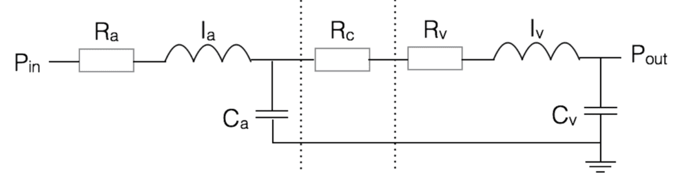
re-drawn as:
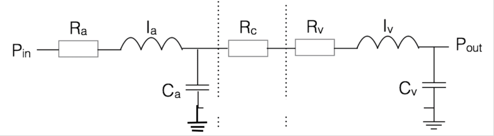
Attempt:
Making the above assumptions, we could use KVL to get an equation for the first junction, which we can denote as ## P_x ## (in ##s##-domain):
[tex]\frac{P_{in} - P_{x}}{R_a + I_a} + \frac{P_{ref} - P_{x}}{\frac{1}{s C_a}} + \frac{P_{out} - P_x}{(R_c + R_v) + s I_v} = 0[/tex]
and an equation for the output junction as:
[tex]\frac{P_x - P_{out}}{(R_c + R_v) + s I_v} + \frac{P_{ref} - P_{out}}{\frac{1}{s C_v}} = i_{out}[/tex]
which then simplifies to: (if ## P_{ref} = P_{out} ##)
[tex]\frac{P_x - P_{out}}{(R_c + R_v) + s I_v} = i_{out}[/tex]
which I can then go on to solve. However, I cannot easily see how this will take the form of an LPF. When re-drawing the circuit above, it looks as if it turned into two potential dividers, each of which had a transfer function of the form:
[tex]\frac{1}{1 + sRC + s^2 LC}[/tex]
When cascaded without making any assumptions about the reference voltage, it looks as if the complete circuit would form a fourth order LPF... I can't seem to reconcile these two viewpoints.
Any help is greatly appreciated.
I was attempting this problem where the aim is to find the output current as a function of the voltage difference ## P_{in} - P_{out} ##. I just have two quick questions about this circuit:
1. If the 'reference voltage' (which I assume is how the ground voltage is referred to) is the same as the output voltage, am I correct in thinking that I can ignore the last capacitor ## C_v##?
2. Am I allowed to re-draw the following circuit such that the bottom connection wire is removed? It doesn't make any difference to my analysis, but just wondering?
3. Does my attempt below look like it is on the right tracks?
re-drawn as:
Attempt:
Making the above assumptions, we could use KVL to get an equation for the first junction, which we can denote as ## P_x ## (in ##s##-domain):
[tex]\frac{P_{in} - P_{x}}{R_a + I_a} + \frac{P_{ref} - P_{x}}{\frac{1}{s C_a}} + \frac{P_{out} - P_x}{(R_c + R_v) + s I_v} = 0[/tex]
and an equation for the output junction as:
[tex]\frac{P_x - P_{out}}{(R_c + R_v) + s I_v} + \frac{P_{ref} - P_{out}}{\frac{1}{s C_v}} = i_{out}[/tex]
which then simplifies to: (if ## P_{ref} = P_{out} ##)
[tex]\frac{P_x - P_{out}}{(R_c + R_v) + s I_v} = i_{out}[/tex]
which I can then go on to solve. However, I cannot easily see how this will take the form of an LPF. When re-drawing the circuit above, it looks as if it turned into two potential dividers, each of which had a transfer function of the form:
[tex]\frac{1}{1 + sRC + s^2 LC}[/tex]
When cascaded without making any assumptions about the reference voltage, it looks as if the complete circuit would form a fourth order LPF... I can't seem to reconcile these two viewpoints.
Any help is greatly appreciated.