Discussion Overview
The discussion revolves around the circuit models of transmission lines, particularly in the context of graduate-level electromagnetic theory. Participants explore the arrangement and interpretation of RLC components in these models, their implications for signal propagation, and the differences between various types of transmission lines.
Discussion Character
- Technical explanation
- Conceptual clarification
- Debate/contested
Main Points Raised
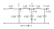
- One participant questions the representation of the circuit model, asking whether the horizontal wires represent parallel plates or if one is a transmission line and the other is ground.
- Another participant describes the model as a transmission line over a ground plane, noting its inductance and capacitance characteristics, and mentions its function as a low-pass filter.
- There is a suggestion that the arrangement of RLC components in the circuit model is based on the physical properties of transmission lines, including series inductance and parallel capacitance.
- A participant points out that while the lumped element circuit has a cutoff frequency, a real transmission line is continuous and does not have a cutoff frequency in the same sense, suggesting the need for more LC sections to accurately model it.
- Another participant references a book by Leon Brillouin that discusses transmission lines from a physics perspective, suggesting it may be beneficial for those with a background in physics/optics.
- There is clarification regarding the model for unbalanced transmission lines, such as coaxial cables, and how it differs from balanced transmission lines, which would include additional inductors in the return leg.
- A later reply emphasizes the importance of including loss terms in the model to accurately reflect the characteristic impedance and its frequency dependence, particularly in practical applications like IoT communications.
Areas of Agreement / Disagreement
Participants express varying interpretations of the circuit model and its implications, with some agreeing on the basic characteristics of transmission lines while others raise questions about the accuracy and completeness of the lumped element model. The discussion remains unresolved with multiple competing views on the representation and behavior of transmission lines.
Contextual Notes
Participants note limitations in the lumped model, particularly regarding its inability to fully capture the continuous nature of real transmission lines and the effects of losses on characteristic impedance.
Who May Find This Useful
This discussion may be of interest to graduate students in electromagnetic theory, professionals working with transmission lines in communications, and those exploring the theoretical underpinnings of circuit models in physics and engineering.