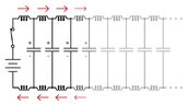
Propagation speed and LC model of transmission line

  • #1
eyeweyew
27
5
TL;DR Summary
If the parasitic capacitor needs to be charged up one by one along the transmission line in order for voltage to propagate, then how can current be so much slower than propagation?
I am a bit confused on the speed of voltage propagation in the transmission line and I hope someone can enlighten me. I understand the speed of voltage propagation is in the same order as the speed of light and it is much faster than current. But if we can model the transmission line with a distributed LC model as the image attached, how can the modelled capacitors got charged so fast at a rate proportional to the speed of voltage propagation if an electron travel much slower? In other words, voltage propagation requires capacitor to be charged up one after another along the transmission line according to the model. If this is the case, that means electrons need to travelling from the + side to the - side in order to charge a capacitor but if electron is indeed traveling very slowly then how can voltage propagate that fast in the transmission line?

Image source: https://www.allaboutcircuits.com/textbook/alternating-current/chpt-14/characteristic-impedance/
 

Attachments

  • 0WkwN.jpg
    0WkwN.jpg
    23.4 KB · Views: 47
Engineering news on Phys.org
  • #2
eyeweyew said:
I understand the speed of voltage propagation is in the same order as the speed of light and it is much faster than current.
Say what? The voltage does not propagate by magic. It takes the current to change the voltage on the distributed capacitance(s).

Can you post a technical link that makes you think that the voltage propagates faster than the current in a transmission line? Thanks.

EDIT/ADD -- Maybe you are asking about the slow drift velocity of electrons in the wires versus the faster propagation of the voltage and current EM waveforms?
 
  • Like
Likes Delta Prime
  • #3
I am referring to the propagation of a step increase in voltage along the transmission line which has speed in the same order as speed of light vs. the drift velocity of electrons which is proportional to current. What I got from reading http://www.sigcon.com/Pubs/edn/LosslessPropagation.htm and https://www.allaboutcircuits.com/textbook/alternating-current/chpt-14/characteristic-impedance is that the propagation speed of a step increase in voltage along the transmission line is proportional to the rate of charging parasitic capacitors along the transmission line in the LC couple series model, i.e., how many modelled parasitic capacitors were charged up per unit time. But charging capacitors requires electrons to move from + side to the - side through the wire/transmission line but the drift velocity of electron is slow so charging up capacitor should also be slow. If that’s the case, how can the propagation speed of a step increase in voltage along the transmission line be so fast?
 
Last edited:
  • #4
:welcome:

eyeweyew said:
if the drift velocity of electron is slow, then how can the propagation speed of a step increase in voltage along the transmission line be so fast?
Here is one, not terribly accurate, way to wrap your brain around it.

The electrons are motivated to move due to the Electric Field. That does NOT mean they travel at the same speed.

An analogy could be a childs toy 'pop gun', those things that shoot a cork using compressed air. When the pop gun is discharged, the cork moves at some speed (maybe 100 feet per second). What we perceive as sound is the compression wave of the air that travel about 1100 feet per second.

Consider the cork to be an Electron and the sound you hear as the Electric Field. You hear the sound before the cork gets to you, so you duck to get out of the way.

I'm sure others here can give a much better technical description, but at least you now have simplified idea of the concept.

Hope this helps!

Cheers,
Tom
 
  • #5
eyeweyew said:
But charging capacitors requires electrons to move from + side to the - side through the wire/transmission line but the drift velocity of electron is slow so charging up capacitor should also be slow.
Not so. The current does not flow through the capacitor, but separately builds up an equal and opposite charge alternately on the electrode surfaces.

As the EM wave propagates along a two conductor line, the cloud of free electrons in the conductor move along the line. What happens in one conductor is reversed in the other conductor.

To understand the capacitive effect of the line, think of the electrons sloshing backwards and forwards locally in the line as the voltage wave propagates. Where it becomes negatively charged, electrons pile up, where it becomes positively charged, electrons move away from. That provides the virtual capacitor voltage.

The inductive effect comes about because the magnetic field propagating along the line induces equal and opposite currents in the conductors. That current, in each conductor, produces an equal and opposite magnetic field that reflects the magnetic field from the conductor. The current that flows matches the voltage on the capacitance of the line, and keeps the EM energy and fields in the line.

The characteristic impedance of the line is the ratio of voltage to current, and also the ratio of the E field to the M field. All those are locked in phase by local electron movement as the EM wave propagate energy along the line.
 
  • #6
Baluncore said:
ratio of the E field to the M field
What's "the M field"?
 
  • #7
DaveE said:
What's "the M field"?
I am keeping it simple, obviously the Magnetic field.
 
  • #8
eyeweyew said:
But charging capacitors requires electrons to move from + side to the - side through the wire/transmission line but the drift velocity of electron is slow so charging up capacitor should also be slow. If that’s the case, how can the propagation speed of a step increase in voltage along the transmission line be so fast?
Ditch the transmission line theory and think of a simple RC network. Same thing. The capacitor can be made to charge up much faster than drift velocity.
-
A very small diameter tube might take a long time for a specific drop of oil to travel from one end to the other, but a pressure gauge may respond very quickly. Similar, but admittedly a rather dodgy analogy.
 
  • #9
Averagesupernova said:
Ditch the transmission line theory and think of a simple RC network. Same thing. The capacitor can be made to charge up much faster than drift velocity.
-
A very small diameter tube might take a long time for a specific drop of oil to travel from one end to the other, but a pressure gauge may respond very quickly. Similar, but admittedly a rather dodgy analogy.

But the most basic RC circuit model requires electrons to travel from/to voltage source to charge the capacitor right? and the time constant is RC. Just want to confirm my fundamental knowledge of circuit is still correct.
 
  • #10
No, the basic RC circuit requires a current of electrons. The electrons in the conductors move from the negative side of the source TOWARDS the positive side. Nothing says they have to make it all the way around.
 
  • #11
eyeweyew said:
But the most basic RC circuit model requires electrons to travel from/to voltage source to charge the capacitor right? and the time constant is RC. Just want to confirm my fundamental knowledge of circuit is still correct.
Humm... I guess you skipped over the previously dodgy analogy. Let me rephrase it.

When you turn on the tap at your sink, you don't have to wait for the first water molecule to travel all the way from the storage reservoir above your town. If they turn off the valve at the dam, you don't have to wait long for you to have no flow at your sink.

The electron that returns to the battery to maintain balance doesn't have to be the same as the one that just left the battery.
 
  • #12
Yes, I understand the analogy. I shouldn't have said electrons need to travel all the way from voltage source to the plate to charge the capacitor. I guess I was misled by some educational videos on youtube. But at least some electrons should've flowed from the wire near the plate to build up charges on the plate so voltage between 2 plates can go up right?
 
Last edited:
  • #13
I'll need to dig more to find useful videos or tutorials, but keep in mind that GHz EM waveforms can propagate down transmission lines, even though the drift velocity of electrons in the metal conductors is so slow. AC waveforms give minuscule movements of electrons in the conductors, but still propagate just fine. :smile:
 
  • #14
eyeweyew said:
Yes, I understand the analogy. I shouldn't have said electrons need to travel all the way from voltage source to the plate to charge the capacitor. I guess I was misled by some educational videos on youtube. But at least some electrons should've come from the wire near the plate to build up charges on the plate so voltage between 2 plates can go up right?
Yes, they do move a bit. It's complicated and depends on the situation. In a capacitor with a dielectric, it may be as subtle as the e-field causing molecules to rotate a little bit, creating a net charge displacement. At a transistor junction it could be just enough to make an electron move to a nearby atom that previously wasn't likely.

But still, the dodgy analogy doesn't explain how you can excite an antenna on earth and make a corresponding electrical signal on a space probe's antenna. No electrons are going to Jupiter to do that. Similar physics can explain how electrical signals can propagate along a wire at nearly the speed of light, they are like waves being guided by the wire. It is better to think of a force traveling along the wire than particles moving in it. That force may then have a local effect; rotating a dielectric molecule, making an electron jump across a transistor junction, or moving electrons a little bit inside a conductor (like in an antenna or a piece of that wire).
 
Last edited:
  • Like
Likes berkeman
  • #15
The whole concept of explaining E&M with lumped element circuit models is fundamentally flawed whenever you look deeply enough. Honestly it's just a really useful approximation to the underlying physics. Schematics never match the real world circuit, with many details intentionally left out. In addition, the underlying method of writing DEs from kirchhoff's laws isn't precisely correct.
 
  • #16
Baluncore said:
Not so. The current does not flow through the capacitor, but separately builds up an equal and opposite charge alternately on the electrode surfaces.

As the EM wave propagates along a two conductor line, the cloud of free electrons in the conductor move along the line. What happens in one conductor is reversed in the other conductor.

To understand the capacitive effect of the line, think of the electrons sloshing backwards and forwards locally in the line as the voltage wave propagates. Where it becomes negatively charged, electrons pile up, where it becomes positively charged, electrons move away from. That provides the virtual capacitor voltage.

The inductive effect comes about because the magnetic field propagating along the line induces equal and opposite currents in the conductors. That current, in each conductor, produces an equal and opposite magnetic field that reflects the magnetic field from the conductor. The current that flows matches the voltage on the capacitance of the line, and keeps the EM energy and fields in the line.

The characteristic impedance of the line is the ratio of voltage to current, and also the ratio of the E field to the M field. All those are locked in phase by local electron movement as the EM wave propagate energy along the line.
So if I understand this correctly, I can summarize this as: At any point on the transmission line, the local capacitor will get charged by local charges nearby and a local current will start as the EM wave(generated by the sudden change in voltage) arrives from the voltage source.
 
  • #17
eyeweyew said:
So if I understand this correctly, I can summarize this as: At any point on the transmission line, the local capacitor will get charged by local charges nearby and a local current will start as the EM wave(generated by the sudden change in voltage) arrives from the voltage source.
Ack.

Have you learned about Maxwell's Equations yet for the propagation of EM? That would be a much better subject for you to spend time studying, IMO...

1694648549275.png

http://hyperphysics.phy-astr.gsu.edu/hbase/electric/maxeq.html
 
  • #19
Would you agree the below video is kind of misleading since it gave me an impression that a lot of electrons move in/out of the two plates from/to the wire to charge the capacitor?

 
  • #20
eyeweyew said:
Would you agree the below video is kind of misleading...
It is only the scale that is misleading. Electrons are much smaller, and trillions of electrons travel less than a micron along the surface of the conductor.

There is a density wave that travels through the electron cloud that decides the voltage on the line. It is shown here.
https://en.wikipedia.org/wiki/Transmission_line.

It is important to realise that the EM field in the dielectric insulation of the line causes the local electrons to move and change density. That movement of electrons is the current that guides and supports the magnetic field, while the electron density changes the voltage on the line, which guides and supports the electric field.
The EM field propagate at close to the speed of light, causing the differential electron density wave to move at that same speed along the line.
 
  • Like
Likes eyeweyew and DaveE
  • #21
Baluncore said:
It is only the scale that is misleading. Electrons are much smaller, and trillions of electrons travel less than a micron along the surface of the conductor.
So it is only the drift velocity that is slow, drift current is not that slow since I = nAvQ, v is low but n is high.

Baluncore said:
There is a density wave that travels through the electron cloud that decides the voltage on the line. It is shown here.
https://en.wikipedia.org/wiki/Transmission_line.
Thanks! The picture explains a lot, at least for AC input. If the input is a sudden step change in voltage by closing the switch without opening it again, the voltage source needs to spit out electrons to one line and pull back electrons from the other line to maintain the density behind the wave.
 
  • #22
eyeweyew said:
TL;DR Summary: If the parasitic capacitor needs to be charged up one by one along the transmission line in order for voltage to propagate, then how can current be so much slower than propagation?

how can the modelled capacitors got charged so fast at a rate proportional to the speed of voltage propagation if an electron travel much slower?

eyeweyew said:
But at least some electrons should've flowed from the wire near the plate to build up charges on the plate
eyeweyew said:
But charging capacitors requires electrons to move from + side to the - side through the wire/transmission line but the drift velocity of electron is slow so charging up capacitor should also be slow

I think these two quotes show the OP's problem. electrons have a mean speed through a wire of around 1mm/s. Individual electrons do not need to move from A to B for the electric current to have an effect. It's the forces between electrons that propagate along a wire and not the electrons themselves.

I will invoke the tried and tested bicycle chain argument. When you slam your foot on the pedal, the wheel starts to turn (almost) immediately; you don't need to wait for those particular links by your foot to travel from the chain wheel to the wheel sprocket. The tension force propagates by the speed of sound in the chain (+/-) and, likewise, the force to move charges in a circuit propagates at just a bit less than c. It's all happened almost before the electrons at one end have found their way into the first few mm of the wire.

The idea of "drift current" is meaningless here. The current OUT is the same as the current IN but just a bit later. That delay is the same as the delay in the voltage change. (Bicycle chain again.)
 
  • Like
Likes Tom.G

1. What is the propagation speed of a transmission line?

The propagation speed of a transmission line is the speed at which an electrical signal travels along the line. It is typically expressed in meters per second (m/s) or feet per second (ft/s).

2. How is the propagation speed of a transmission line calculated?

The propagation speed of a transmission line can be calculated by dividing the speed of light (approximately 3 x 10^8 m/s) by the square root of the relative permittivity and relative permeability of the medium in which the line is propagating.

3. What is the LC model of a transmission line?

The LC model of a transmission line is a simplified representation of a transmission line as a series of inductors (L) and capacitors (C). It is used to analyze the behavior of a transmission line and can be used to calculate its characteristic impedance and propagation speed.

4. How does the LC model of a transmission line relate to the physical structure of the line?

The inductors in the LC model represent the inductance of the conductors in the transmission line, while the capacitors represent the capacitance between the conductors. The values of these components are determined by the physical dimensions and materials of the transmission line.

5. What are the limitations of the LC model of a transmission line?

The LC model is a simplified representation and does not take into account factors such as resistance, skin effect, and dielectric losses. It also assumes that the transmission line is uniform and infinitely long, which may not be the case in practical applications.

Similar threads

Replies
8
Views
1K
Replies
11
Views
1K
Replies
2
Views
1K
Replies
8
Views
1K
  • Electromagnetism
Replies
4
Views
978
Replies
69
Views
7K
  • Electrical Engineering
Replies
1
Views
1K
  • Engineering and Comp Sci Homework Help
Replies
18
Views
2K
Replies
1
Views
961
  • Electrical Engineering
3
Replies
73
Views
7K
Back
Top