Ranking charge stored on three capacitors by a battery

Click For Summary

Homework Help Overview

The discussion revolves around understanding the charge stored on three capacitors connected to a battery, focusing on the assumptions made regarding their initial charge states and the implications for their final charge distribution in steady state.

Discussion Character

  • Conceptual clarification, Assumption checking, Problem interpretation

Approaches and Questions Raised

  • Participants explore the assumption that capacitors are initially uncharged and question its necessity. They discuss the relationship between capacitance and charge, raising concerns about the ranking of charges based on capacitance values. Some participants suggest solving for charges and voltages to clarify the ranking.

Discussion Status

There is an ongoing examination of the assumptions and interpretations of the problem. Some participants have offered guidance on identifying series and parallel configurations of the capacitors, while others are reflecting on their understanding of Kirchhoff's Voltage Law (KVL) and its application in this context.

Contextual Notes

Participants note the importance of correctly identifying the configuration of capacitors and the implications of voltage across them when comparing stored charges. There is a recognition of potential confusion regarding the conservation of charge in the circuit.

member 731016
Homework Statement
Please see below
Relevant Equations
Please see below
For this problem,
1675976058981.png

The solution is,
1675976090665.png

I have a few questions about parts of the solutions,
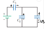
- Part(b):

(1) Why do they assume that the capacitors are initially uncharged? Do they even need to make that assumption because it seems clear to me that we are finding the charge stored by each capacitor once the circuit has reached steady state. Would it not be better to say assume capacitors ##C_1##, ##C_2## and ##C_3## are charged?

(2) How did they get ## Q_1 > Q_3 > Q_2 ##? I don't understand their statement about if the capacitors are initially uncharged then ##C_1## stores the same charge as ##C_2## and ##C_3## in steady state. I though the answer should be ##Q_2 < Q_1 < Q_3 ## as it should be in the order from smallest to largest capacitance since ##Q ∝ C## (from ##C = \frac {Q}{V}##), correct?
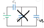
- Part(d):

(3) I don't understand why the charge ##Q## increases from ##Q_i## to ##Q_f##. I thought charge would be conserved in this circuit, why is it not conserved?

Many thanks!
 
Physics news on Phys.org
They don't have to assume that the capacitors are initially uncharged. I can see why the ranking done conceptually could be confusing to you. Perhaps you can do it by actually solving for the charges and the voltages. Remember that the sum of voltage drops and rises around a closed loop is zero.

Callumnc1 said:
as it should be in the order from smallest to largest capacitance since ##Q \propto C##
If you compare charge stored in capacitors, the capacitor with the larger capacitance is guaranteed to hold more charge only if the voltage across the capacitors is the same. In ##Q=CV##, if you want to compare ##Q##s you cannot only look at ##C## and ignore ##V##.
 
  • Like
Likes   Reactions: member 731016 and PhDeezNutz
kuruman said:
They don't have to assume that the capacitors are initially uncharged. I can see why the ranking done conceptually could be confusing to you. Perhaps you can do it by actually solving for the charges and the voltages. Remember that the sum of voltage drops and rises around a closed loop is zero.If you compare charge stored in capacitors, the capacitor with the larger capacitance is guaranteed to hold more charge only if the voltage across the capacitors is the same. In ##Q=CV##, if you want to compare ##Q##s you cannot only look at ##C## and ignore ##V##.
Thank you for your reply @kuruman ! Thank you for reminding me for looking at ##V##!

So in terms of proving their ranking ## Q_1 > Q_3 > Q_2 ## symbolically, do you know what steps I have done wrong please?

Finding the equivalent capacitance of the circuit,

##C_{eq} = 2C = \frac {Q}{V_1 + V_2 + V_3} = \frac {Q}{\epsilon}##

Adding up the positive charge on each plate,

##Q_1 + Q_2 + Q_3 = Q##

Applying KVL to circuit,

##\epsilon = V_1 + V_2 + V_3 ##

##\epsilon = \frac {Q_1}{C_1} + \frac {Q_2}{C_2}+ \frac {Q_3}{C_3} ##

## \frac {Q}{2C}= \frac {Q_1}{C_1} + \frac {Q_2}{C_2}+ \frac {Q_3}{C_3} ##

## \frac {Q_1 + Q_2 + Q_3}{2C} = \frac {Q_1}{C_1} + \frac {Q_2}{C_2}+ \frac {Q_3}{C_3} ##

## \frac {Q_1 + Q_2 + Q_3}{2C} = \frac {Q_1}{3C} + \frac {Q_2}{C}+ \frac {Q_3}{5C} ##

## \frac {Q_1 + Q_2 + Q_3}{2C} = \frac {5Q_1C^2 + 15Q_2C^2 + 3Q_3C^2}{15C^3} ##

## 7.5C^2(Q_1 + Q_2 + Q_3) = 5Q_1C^2 + 15Q_2C^2 + 3Q_3C^2 ##

## 7.5Q_1 + 7.5Q_2 + 7.5Q_3 = 5Q_1 + 15Q_2 + 3Q_3##

Many thanks!
 
I don't think you know what you are doing. The first thing you need to do is to identify which capacitors are in series and which are in parallel, not assume that they are all in series which is what your equations say. This identification is done for you in the solution which you ignored for some reason. Your application of KVL is incorrect. You just don't set the sum of all possible potential differences equal to the battery voltage. If you don't remember how to use KVL, please read up on it.
 
  • Like
Likes   Reactions: member 731016
kuruman said:
I don't think you know what you are doing. The first thing you need to do is to identify which capacitors are in series and which are in parallel, not assume that they are all in series which is what your equations say. This identification is done for you in the solution which you ignored for some reason. Your application of KVL is incorrect. You just don't set the sum of all possible potential differences equal to the battery voltage. If you don't remember how to use KVL, please read up on it.
Thank you for your reply @kuruman!

##C_1## is in series with the battery
##C_2## and ##C_3## is in parallel with the battery

Since ##C_2## and ##C_3## are parallel to each other their equivalent capacitance is ##C_2 + C_3##.

I think what I did wrong with KVL was that I did not finding the equivalent capacitance of the capacitors in parallel.

So if I replace branch's ##C_2## and ##C_3## with ##C_{23}## I get:
1675994162675.png

So now ##V_1## and ##V_{23}## oppose the source, I think.

##\epsilon - V_1 - V_{23} = 0 ##
##\epsilon = V_1 + V_{23} ##

So I think what I did wrong was that I applied KVL for the whole loop.

Many thanks!
 

Attachments

  • 1675994074135.png
    1675994074135.png
    1.6 KB · Views: 144
  • 1675994385504.png
    1675994385504.png
    1.3 KB · Views: 156
That's much better.
 
  • Like
Likes   Reactions: member 731016
kuruman said:
That's much better.
Thank you @kuruman !
 

Similar threads

  • · Replies 11 ·
Replies
11
Views
3K
Replies
4
Views
2K
  • · Replies 4 ·
Replies
4
Views
2K
  • · Replies 30 ·
2
Replies
30
Views
3K
  • · Replies 16 ·
Replies
16
Views
2K
Replies
2
Views
2K
Replies
3
Views
2K
  • · Replies 7 ·
Replies
7
Views
1K
  • · Replies 21 ·
Replies
21
Views
3K
  • · Replies 4 ·
Replies
4
Views
4K