Receiver Circuit Question -- What role does this antenna capacitor play?

In summary: That website appears to have good explanations of each part of the circuit (cool website, BTW). Is there a part of their explanations that you are having trouble with?I'm having trouble understanding the importance of the antenna coupling capacitor. The website says it's "a critical component in a regenerative receiver without an RF stage," but it doesn't say what its job is.
  • #71
Baluncore said:
Your irrational line breaks make it hard to understand your reasoning.

If the only losses were the series resistance of the inductor, or the dielectric losses of the capacitor, then the wikipedia simplicity would be correct.

But in the real world there are other networks in parallel with L and C that lower the Q. There is no advantage in having an isolated tuned circuit if it does not have energy inputs and energy outputs.

Ok, maybe I understand your point and the reason for my confusion now (correct
me if I'm wrong):

Seemingly we talked past each other on the point what the considered "tuned circuit" should be.
So I guess that you implicitely considered the antenna impedance + the coupling capacitor
as part of it, while I (wrongly?) assumed that when you talked about "tuned circuit" you literally
only mean this LC-thing. In pictures:
tuned circuit Baluncore.png


Well, if you indeed meant by "tuned circuit" the blue encircled thing, then clearly it's Q depends on the coupling capacitor (I conjecture that you meant exactly this thing because as you said the Q of it should depend on antenna losses, while the Q of the green encircled thing has - as wiki formula says - no dependence on the antenna components & coupling capacitor. Did understood your point now correctly?
 
Engineering news on Phys.org
  • #72
The Tortoise-Man said:
Seemingly we talked past each other on the point what the considered "tuned circuit" should be.
So I guess that you implicitely considered the antenna impedance + the coupling capacitor
as part of it, while I (wrongly?) assumed that when you talked about "tuned circuit" you literally
only mean this LC-thing.
No.
You cannot draw lines sensibly about components that are connected with wires, because signals travel both ways on the wires and the lines cannot form secure bulkheads.

The tuned circuit is the LC resonant circuit, where energy is circulated between L and C. That may have internal losses that set the maximum Q.

The tuned circuit is also externally loaded.
The external resistive loads further reduce the Q of the tuned circuit.
The external reactive loads change the frequency of the tuned circuit.
 
  • #73
The Tortoise-Man said:
Ok, maybe I understand your point and the reason for my confusion now (correct
me if I'm wrong):

Seemingly we talked past each other on the point what the considered "tuned circuit" should be.
So I guess that you implicitely considered the antenna impedance + the coupling capacitor
as part of it, while I (wrongly?) assumed that when you talked about "tuned circuit" you literally
only mean this LC-thing. In pictures:
View attachment 292775

Well, if you indeed meant by "tuned circuit" the blue encircled thing, then clearly it's Q depends on the coupling capacitor (I conjecture that you meant exactly this thing because as you said the Q of it should depend on antenna losses, while the Q of the green encircled thing has - as wiki formula says - no dependence on the antenna components & coupling capacitor. Did understood your point now correctly?
For what it is worth @The Tortoise-Man, I agree with your above statement. My reading of this thread brought me to the same conclusion you reached.

Cheers,
Tom
 
  • #74
Baluncore said:
No.
You cannot draw lines sensibly about components that are connected with wires, because signals travel both ways on the wires and the lines cannot form secure bulkheads.

The tuned circuit is the LC resonant circuit, where energy is circulated between L and C. That may have internal losses that set the maximum Q.

The tuned circuit is also externally loaded.
The external resistive loads further reduce the Q of the tuned circuit.
The external reactive loads change the frequency of the tuned circuit.
I'm confused. Maybe I just too stupid and too wikipediazed to understand your interpretation of Q. I thought that it's always possible in an arbitrary circuit to associate to every bunch of neighboured components a Q, which depends only of the parameters of these components and not external components,

Example Circuit.png


eg that in following simple circuit we can associate a factor Q-factor ##Q_{L1C1R1}## to L1-C1-R1-unit only, but also eg a ##Q_{L2R2}## to L2-R_L-only only, even to any individual reactive component(https://en.wikipedia.org/wiki/Q_factor#Individual_reactive_components),
like C2 alone, if we realize that real C2 has a small real restance. Of course we can associate a Q to the total circuit. The point I want lake to emphasize is Q's modularite I assumed.

And I thought that this Q always depends only on the components to which it is associated, not the external one. But you said that's not the case, so it depends on external components, and I have to admit that sound like a culture shock to me, nevertheless I would like to understand your point better.

If it's ok for you, could we go one step back? What is your precise definition of Q? And assume we have an example circuit like the above, consider it as a kind of "playground". According to your definition
of Q, to which components or sub parts of this circuit you can associate a Q?

How do you calculate it? As far as I understand you correctly, you not get the formulas I found in wikipedia. Could you give an example calculation of some component of this circuit? Or could you give a reference where the Q is discussed in the way you explained it? Ie that it depends also on external components?
 
  • #75
The Tortoise-Man said:
I thought that it's always possible in an arbitrary circuit to associate to every bunch of neighboured components a Q, which depends only of the parameters of these components and not external components,
Find an "energy flywheel" such as a resonant LC circuit with some R. As an isolated circuit it will have a Q. That is the extent of the wikipedia analysis. That Q is a maximum for the greater circuit.

Then study all the ways the resonator can lose energy to the surrounding environment. How will the choice of external components change the rate of energy loss? Those external loads will lower the Q of the greater circuit to below the wikipedia calculated maximum.

In this case a larger coupling capacitor would increase the losses through the anttenna, so it would reduce the Q of the greater circuit.
 
  • #76
Baluncore said:
Then study all the ways the resonator can lose energy to the surrounding environment. How will the choice of external components change the rate of energy loss? Those external loads will lower the Q of the greater circuit to below the wikipedia calculated maximum.

In this case a larger coupling capacitor would increase the losses through the anttenna, so it would reduce the Q of the greater circuit.

Ok, I think I understand your point. So if we want to study the Q factor of a LC-circuit in the sense you thinking about it, one can rephrase to idea as follows on following elementary example:

Say as an example we want to analyse the function Q of a elementary parallel
LCR circuit in the sense you think about is:

LCR Parallel Circuit.png
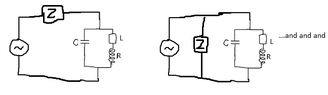
Then this Q is a function of the three components ##L, C, R## components and the impedance
##Z_E=R_E+jX_E## of an abstract environment component which we can attach to the "scaffold of
the total circuit"

LCR Parallel Circuit AC.png


in any feasible way we want, like eg

LCR Parallel Circuit Attach Z.png
ie any configuration how can we attach a or more environment component(s) to this scaffold of
the circuit is allowed.

How to calculate this ##Q (=Q(L, C, R; Z_E))## for a
given environment component with impedance ##Z_E##?

We calculate the ##Q(L, C, R; Z_E)## just as the Q of the TOTAL circuit, ie with the LC-circuit and
the environment component by the techniques from wikipedia/ "stadard textbook methods" how to calculate the Q faction of a fixed circuit.

Eg if the environment compoent is a capacitor parallel to the the LCR-circuit the Q(L, C, R; Z_E) equals to the Q of the total circuit:
LCR Parallel Circuit Red Q.png

Finally, we observe that the "wikipedia/textbook" Q of the LC-circuit consides with the case when
there is no environment compoent, ie Q= Q(C, L, R; -):

LCR Parallel Circuit LCR Alone.png


Did I understood your idea of the Q factor now correctly?
 

Attachments

  • LCR Parallel Circuit Attach Z.png
    LCR Parallel Circuit Attach Z.png
    3.2 KB · Views: 73
  • #77
The Tortoise-Man said:
Say as an example we want to analyse the function Q of a elementary parallel
LCR circuit in the sense you think about is:

lcr-parallel-circuit-png.png
That's a series resonance. Sorry for nit-picking though. In a series configuration low loss requires low resistance. In a parallel configuration low loss requires high resistance.

The Tortoise-Man said:
Did I understood your idea of the Q factor now correctly?
Yes, I think you've got it. More complex networks can get confusing though and people will either disagree or be sloppy about what Q is. In those cases, I prefer the basic physics approach, where Q is simply an expression of the energy loss that the reactive resonant elements experience. Of course, while the concept is simple, the calculations aren't always. The biggest confusion arises when a network has more than one resonance. I claim each resonance has its own Q (a more mathematical approach), others disagree and will assign a more global definition; one Q for everything (a more functional approach). We are both right, in the proper context. So, for more complex networks, you'll just have to explain the version you are using, I think.
 
  • #78
The Tortoise-Man said:
Say as an example we want to analyse the function Q of a elementary parallel
LCR circuit in the sense you think about is:

lcr-parallel-circuit-png-png.png

DaveE said:
That's a series resonance.
I'm curious @DaveE, if that is a series resonant circuit, could you please show us/draw a parallel resonate circuit?

Thanks.
 
  • #79
The Tortoise-Man said:
Ok, I think I understand your point.
Your symbol for a zero impedance AC voltage source, that short circuits the tuned circuit confuses things. For this analysis, I simply assume there will be one unit of energy circulating in the tuned circuit at the start of the analysis.

The antenna is a load impedance, Zant.
If you later need a signal from the antenna to model the gain of the circuit, insert a voltage source, Vant in series with the antenna Zant. But that signal source is not needed to understand or model the resonant circuit.
 
  • Like
Likes DaveE
  • #80
20211124_160621.jpg


The mathematical version of Q goes like this:

That quadratic term in the impedance can be expressed in a canonical form of ##(1+\frac{1}{Q}(\frac{s}{\omega_o})+(\frac{s}{\omega_o})^2)##

Then, you will find that ##\omega_o = \frac{1}{\sqrt{LC}}##, ##Z_o = \sqrt{\frac{L}{C}}## (the characteristic impedance).

For the series resonator, ##Q = \frac{Z_o}{R}##

For the parallel resonator, ##Q = \frac{R}{Z_o}##

These circuits and canonical forms are worth memorizing, IMO. You'll see it in electronics, mechanics, acoustics... everywhere. It is the solution to the simple harmonic oscillator with losses.

Each pole or zero in the transfer function (impedance, gain, whatever...) will either be a single Real value, or it will be a quadratic pair. Those quadratic pairs of roots (or zeros) are each Complex and can be characterized by their frequency (##\omega_o##) and their Q.

However, while all of this is true, it is also a particular analytical method that is favored by some and not by others. If you study control systems, filter design, etc. then this is how you think. If you study how to actually build radios like people in the 1930's then you speak in different terms about the same concepts.
 
  • #81
Baluncore said:
that signal source is not needed to understand or model the resonant circuit.
Yes, this is an important concept. A bell is a resonant structure whether you ring it or not. The resonance is all about what happens after you've put some energy in, not so much about where the stimulus came from.
 
  • #82
Ok, so it's a matter of nomenclature. If we replace 'parallel LCR circuit' everywhere I wrote it by 'series circuit' as Dave in #77 suggested.

And furthermore if we remove everywhere in my images in #76 the AC voltage source ~ as
Baluncore suggested and instead think of it that in all circuits I draw there is a fixed one unit of energy circulating:

Is then what I wrote about my attempt to understand Baluncore's
interpretation of Q factor after making correction on these two points in
post #76 correct?
 
  • #83
Correct.
 
  • #84
By the way: recently there came another simple idea into my mind how maybe role of red tagged capacitor ('the coupling capacitor') from my post #1 (which was my initial problem with this circuit) might be understood in more simple terms if someone is not completely familiar with this stuff around "Q factor" or feels at least uncomfortable in it as follows:

namely, is it correct that the part
Bandpass Filter.png


as a whole may be recognized as a bandpass filter, and the indispensability of the coupling capacitor here is expressed in the fact that without it the blue encircled part simply would not be a bandpass filter any more. So the coupling capacitor is necessary to complete it's functionality as a bandpass filter.

Is this interpretation of the role of the coupling cap also correct? Or does it here missing the point?

(indeed I pondered a while why if the blue encircled unit is indeed a bandpass filter there are two capacitors C2 and C3 in the tank used. My conjecture: the reason why they coexist there might be that the receiver circuit above is designed to receive frequencies from two disjoint bands. If the desired frequence lies in one band, C2 is used to tune it, if on the other, then C3 does the job; is this interpretation correct?)
 
  • #85
Look up the definition of bandspread and bandset it will likely answer your question.
 
  • #86
Averagesupernova said:
Look up the definition of bandspread and bandset it will likely answer your question.
Ok, this answers why the tank in #84 could have two capacitors C2 and C3, right? So essentially that allows a qualitatively more advanced control over tuning the desired frequence?

Ok, what about my 'attept' to interpret the red encircled coupling capacitor as functional part of the blue encircled unit: Is the only job of this blue unit indeed the bandpass filtering and is then as I conjectured the job of the coupling cap just to coplete it (since otherwise it would not be a bandpass filter)?
 
  • #87
Think of it this way: Anything you attach to a tank circuit will lower the Q. Being able to adjust the amount of coupling will affect this.
 
  • #88
The Tortoise-Man said:
So the coupling capacitor is necessary to complete it's functionality as a bandpass filter.
Is this interpretation of the role of the coupling cap also correct? Or does it here missing the point?
There is no bandpass filter, only the tuned circuit. You are missing the point.
The Q of the front end is roughly; Q = (C2+C3) / C1.
That is because AC current is shared in proportion to capacitance; i ∝ C · dV/dt .
For a fixed C1, as you tune across the band, (C2+C3) changes, so the Q must also change.
C1 allows you to adjust the Q and the degree of antenna coupling to the signals of interest.
 
  • #89
Baluncore said:
There is no bandpass filter, only the tuned circuit. You are missing the point.
The Q of the front end is roughly; Q = (C2+C3) / C1.
That is because AC current is shared in proportion to capacitance; i ∝ C · dV/dt .
For a fixed C1, as you tune across the band, (C2+C3) changes, so the Q must also change.
C1 allows you to adjust the Q and the degree of antenna coupling to the signals of interest.
I'm not completely convinced. For our considerations about the issue 'Is it
a bandpass filter or not' we can drop the third capacitor C3 (as Averagesupernova
noted the precence of two capacitors C2 and C3 has only to do with bandspread issues;
let's forget it in next considerations) and consider the simplified version of right picture
in #84:

BANDPASS MODEL Bandpass Filter.png


Then as you said it's Q is proportional to C2/C1, right? If the C1 and C2 a variable like
in case of our circuit on the left in #84, isn't the unit in the picture above
nothing but a possible design of "variable" bandpass filter is the sense that if we fix some C1 and C2 it would become a "usual" bandpass filter?

The reason why I think so is that essentially that's what a bandpass filter should do, to let passing signals of desired frequence and block the others deviating from the resonance frequence. And it's "sharpness" on doing that is quanified by the Q factor, right?

Or is your statement that this circuit by construction cannot be a bandpass filter (because eg maybe there is something missing?)
 
Last edited:
  • #90
The Tortoise-Man said:
Or is your statement that this circuit by construction cannot be a bandpass filter (because eg maybe there is something missing?)
Without an input there is no point having a receiver.
The energy input from the antenna can be coupled into the tuned circuit by a tap on the inductor, or by a small value capacitor. The tuned circuit is required no matter which way it is done. The coupling capacitor does not provide an additional band-pass feature to the circuit.

A band-pass filter is distinct from a tuned circuit in that the BPF has steep sides with a flatter top. Stagger tuned circuits can be lightly coupled to make a BPF. But here there is only one tuned circuit.

If you were to model the antenna as a tuned circuit, then couple it through C1 to the L//C2 tuned circuit, you might claim it becomes a BPF. But the antenna for MW is under-size, so is a wider-band structure, not a tuned circuit by itself.
 
  • #91
Baluncore said:
Without an input there is no point having a receiver.

I'm confused, I not understand the train of thought here. What do you mean by
'Without an input there is no point having a receiver.'?

The input is simply on the left side, it can be eg an antenna, a generator,... Why you assuming
that there could be no input? Could you clarify what you mean by this remark?

Baluncore said:
A band-pass filter is distinct from a tuned circuit in that the BPF has steep sides with a flatter top. Stagger tuned circuits can be lightly coupled to make a BPF. But here there is only one tuned circuit.
Yes, of course a tuned circuit alone cannot be BPF. My incorrect conjecture was
that is may become a BPF if we consider it together with C1 in series (ie the circuit from #89)
but as you remarked that's wrong as one may check oneself eg by considering a
simulation plotting the output power as a function of frequency.
If circuit from #89 would be a BPF the power output function should have a
"bell-shaped", but that's not the case here.

I think that's might be the most simple way to see that this circuit can never be a BPF for
all the time.
Baluncore said:
If you were to model the antenna as a tuned circuit, then couple it through C1 to the L//C2 tuned circuit, you might claim it becomes a BPF. But the antenna for MW is under-size, so is a wider-band structure, not a tuned circuit by itself.

Here you probably refer to the observation that if we slightly modify the circuit from #89 by adding a coil in series with appropriate parameter L1, then the following circuit should become a BPF (of cource if C1, L, C2 are choosen in sophisticated way), right?

BANDPASS MODEL Bandpass Filter COIL.png
 
  • #92
The Tortoise-Man said:
Here you probably refer to the observation that if we slightly modify the circuit from #89 by adding a coil in series with appropriate parameter L1, then the following circuit should become a BPF (of cource if C1, L, C2 are choosen in sophisticated way), right?
No, I do not. How would you like to be dragged through a blackberry bush backwards? That is what you seem to be trying to do to me here.

The Tortoise-Man said:
Why you assuming that there could be no input? Could you clarify what you mean by this remark?
For completeness. Can you think of a reason why an input is needed ?
Then how many ways are there to inject that energy, without killing the Q of the front-end ?
 
  • #93
Baluncore said:
No, I do not. How would you like to be dragged through a blackberry bush backwards? That is what you seem to be trying to do to me here.
Ok sorry, then I have misinterpreted your idea
where you wrote:

"If you were to model the antenna as a tuned circuit, then couple it through C1 to the L//C2 tuned circuit,
you might claim it becomes a BPF. "I assumed that there you referred to an antenna model of shape
like this:

ANTENNA Model.png
And since I found in the net (http://www.elektronik-bastler.info/stn/lc_filter.html ;unfortunately in german)
a bandbass filter having the shape of the image in #91, I conjectured
that this L1C1-unit in series was exactly that part which the "bare"
LC2-tank needed to become a honest BPF. Sorry, wrong resonings.
 
  • #94
Baluncore said:
For completeness. Can you think of a reason why an input is needed ?
Then how many ways are there to inject that energy, without killing the Q of the front-end ?

I'm not sure on what you're getting at here. By "killing" Q (of the tank) you mean to make it small as possible, right?
 
  • #95
Yes, killing the Q of a resonant tank circuit means adding more loss, so it rings less and the resonant signal level is lower. Have you looked up resonant tank circuit links yet? (sorry, I haven't been following this thread for a while)
 
  • Like
Likes DaveE
  • #96
The Tortoise-Man said:
Ok sorry, then I have misinterpreted your idea where you wrote:
"If you were to model the antenna as a tuned circuit, then couple it through C1 to the L//C2 tuned circuit, you might claim it becomes a BPF. "
But IF you did that you would be wrong.
The short antenna used prevents there being a second tuned circuit, so there can be no hypothetical BPF. I cannot understand why you insist on returning to discussion of the non-existent, mythical BPF.
You would do better finding out why such a simple regenerative receiver can work so well and how it can be so sensitive and selective.
berkeman said:
Have you looked up resonant tank circuit links yet?
That is good advice.
 
  • Like
Likes berkeman
  • #97
berkeman said:
Yes, killing the Q of a resonant tank circuit means adding more loss, so it rings less and the resonant signal level is lower. Have you looked up resonant tank circuit links yet? (sorry, I haven't been following this thread for a while)
Which "links" do you mean? Did you provide earlier during this lengthy discussion somewhere some recommendable links about resonant tank circuits? I have to admit that I don't have an overview of all the posts here now, sorry if posted some link before and not found it.

Or do you want to know if I searched about
resonant tank circuits on my own? Well, if you indeed mean the second one then what I found is not really satisfying in light
of the course this discussion. What I found about resonant tank circuits can be found summarized
on wikipedia (https://en.wikipedia.org/wiki/LC_circuit), especially the parts on "Series and Parallel
Circuits", that's what have known before.

The new aspects which I learned here (and I didn't know before and which confused me at fist time)
is that (if I understood Baluncore correctly) then when we are talking about Q of tuned circuit
(ie barely that's the red thing in #68 or the green encircled thing in #1) then
it's Q hardly depends which components are there on the left in the "black box",
ie the Q of the tuned circuit not only depends on R, L, C as suggested
suggested on the wikipedia site. That's what what confused me before since I assumed that
if one is talking about Q factor of tuned circuit, then this Q literally depends only on it's
components R, L, C and not what is connected externally to it.

So for example the Q of the tuned circuit depends on the coupling capacitor and the antenna
itself (in #1). See also my posts #76 & corrections in #82. That's how I understand
the concept behind the Q factor of ther tuned circuit now.

Unfortunally I still haven't found a book/ online script where the concept of Q is taught exactly
in this way, that unsettles me a bit if that's how I think about it is really the correct way.
Could you recommend a source which discusses the concept of Q in this spirit?
 
  • #98
The Tortoise-Man said:
Unfortunally I still haven't found a book/ online script where the concept of Q is taught exactly in this way, that unsettles me a bit if that's how I think about it is really the correct way.
There is no "correct" way, it depends on your viewpoint. Anything you believe today may be changed tomorrow. You will not survive long in the real world if you demand certainty.

Keep an open mind and accept that some words can have several meanings in different fields. Learn to think in many alternative reasonable interpretations.
https://en.wikipedia.org/wiki/Postmodernism
 
  • Like
Likes DaveE
  • #99
Baluncore said:
But IF you did that you would be wrong.
The short antenna used prevents there being a second tuned circuit, so there can be no hypothetical BPF. I cannot understand why you insist on returning to discussion of the non-existent, mythical BPF.
You would do better finding out why such a simple regenerative receiver can work so well and how it can be so sensitive and selective.
That was just a spontaneously conjecture of mine. Forgive me if it gets the impression that I
"insist" that there "must" be somewhere a BPF. I threw it just in the room because the
shape of the blue encircled components in #84 reminded me a bit of the structure of BPF circuits.
So I was just wondering if there might be a relation... I not intended to insist that
this has an interpretation as a BPF, I was just curious if there might be some relation due to my
association with BPF circuits I saw before.

But as you said seemingsly I was thinking in totally wrong direction.

Nevertheless, in general receiver circuits it's a natural practise to use BPF's as functional component to naturally filter out some undesired frequences, do you argree with me? If yes, that's basically my motivation why I was wondering if there might be some relation to BPF in this part of the depicted receiver.

But is the reason that in THIS concrete regenerative receiver the blue encircled components
in #84 cannot be interpreted as BPF as you said due to special nature of regenerative receiver's
(ie the usage positive feedback) or does this missing the point and you intended to empasise another aspect?
 
  • #100
Baluncore said:
There is no "correct" way, it depends on your viewpoint. Anything you believe today may be changed tomorrow. You will not survive long in the real world if you demand certainty.

Keep an open mind and accept that some words can have several meanings in different fields. Learn to think in many alternative reasonable interpretations.
https://en.wikipedia.org/wiki/Postmodernism
Yes. This.

In the complex world of RF circuits, people can be sloppy when discussing the concept of Q.

It is all based on the simple harmonic oscillator (SHO) and the physical description of energy lost compared to energy stored per cycle. This is equivalent to the simple RLC circuit. We all know that version and are on the same page.

But, it can be useful to model more complex circuits with these simpler tools. It's how people are applying the simple concept as an approximation of complex circuits that is confusing. You must learn the basics first, and then discuss (or decipher) how it is being used in any real world context. There just isn't going to be the simplicity or consistency you seek. In a pedantic sense, when people discuss Q it is either simple and correct, like in my post #80, or they are (intentionally) a bit wrong.

In practice, it is often used to describe how resonant or how lossy a circuit with stored energy is. This can appear in many different guises.
 
  • #101
The Tortoise-Man said:
BPF ... BPF ... BPF ... BPF ... BPF ... BPF ... BPF
You are still not cured. Can you not let it go ?
You need to be vaccinated against your BPF mind virus.
 
  • #102
Baluncore said:
You are still not cured. Can you not let it go ?
You need to be vaccinated against your BPF mind virus.

Well doctor, what is wrong with it? Wasn't my concern in two last paragraphs of #99 clear enough? I think that such question arise quite naturally at that point. And I would like to appreciate to understand "what is wrong" in my reasonings concretely. We should talk here about science, not mysticism.
 
  • #103
Thread is on time-out... :wink:
 
  • Like
Likes DaveE

Similar threads

  • Electrical Engineering
Replies
9
Views
1K
Replies
14
Views
6K
  • Introductory Physics Homework Help
Replies
2
Views
5K
Back
Top