Homework Help Overview
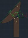
The discussion revolves around calculating the minimum force required to either hold or pull an inclined object (K1) downwards to another position (K2) at an angle of 50 degrees. The object has a mass of 3.5 tons and specific dimensions, with mounting points involved in the setup.
Discussion Character
- Exploratory, Assumption checking, Problem interpretation
Approaches and Questions Raised
- Participants inquire about the center of mass of K1 and the application point of the pulling force. There are discussions about the effects of gravity and wind loading on the object. Some participants question whether the scenario is a real-world problem or an academic exercise, and they differentiate between the forces needed to hold the object steady versus those required to pull it into position.
Discussion Status
The discussion is ongoing, with participants providing guidance on considerations such as the center of mass and torque. There is a recognition of the need for further clarification on the nature of the problem and the specific forces involved. Multiple interpretations of the problem are being explored, particularly regarding the distinction between holding and pulling forces.
Contextual Notes
Participants note the importance of understanding the real-world implications of the problem, including potential wind effects and the need for professional engineering input before any construction. There is also a mention of the specific shape of the object, which may affect the calculations.