Shear and Moment diagram for frame question

Join the discussion
Registration is free. Ask a follow-up in this thread, or start your own.
12 replies · 10K views
getbuckets68
Messages
7
Reaction score
0
Draw the shear and moment diagrams for each of the three members of the frame. Assume the frame is pin connected at A, C, and D and there is a fixed joint at B.
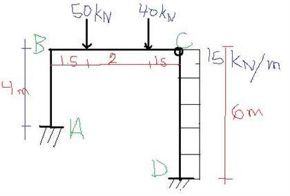
PWuTxuL.jpg


Please i need help with this .. would be great if anyone can help
 
Physics news on Phys.org
First, determine the reactions at A and D to keep the frame in equilibrium.
 
on A i got 101 KN up and 90 KN to right, at D i got -11 Kn , i am not sure if these are right
 
Last edited:
Well, that's easy to check.

Take your reactions an see if they equations of equilibrium are satisfied.

If not, rinse and repeat.
 
think i got the reactions correct but I am not sure bout my shear diagram doesn't look right
 
Well, I'm not sure either. You'll have to post it.
 
ok here is what I've drawn so far
 

Attachments

  • IMG_20130922_153514.jpg
    IMG_20130922_153514.jpg
    7.8 KB · Views: 2,012
It's kinda blurry - can't make out any details at all.
 
dw about the pic uptop just the shear diagram..does the shape look right
 
How do you know the reactions are right? There is no point drawing the moment and shear diagrams if the reactions are not right. The reactions are checkable. So please send your calcs.
 
i already sent my calculations. on reaction A i got 101 KN up and 90 KN to right, on reaction D i got -11 Kn downwards, i am going with these thanks for your help
 
I haven't seen calcs for reactions, which I believe are self-evidently not correct. (For example, what is the bending moment at point C? I am sure you would say 'zero' because of the hinge there, but have you checked by taking the algebraic sum of moments on each side of C?)
 
yes i am re doing the calculations now.. i will take a section at pin C and start summing from there