Mirek2010
- 6
- 0
- TL;DR
- Stuck with simple LS153 multiplexer circuit
Hello,
I am hoping that you could help me understand why my simple circuit is not generating any outputs.
I used LS153 to design a circuit giving two outputs (4 to 1 conversion) on SIMETRIX.
The circuit when 'run' gets the required inputs (as I see them as a square waveform graphs) but the device is not generating outputs.
Would you be able to spare a moment to offer some clues as to what might be missing?
The inputs generated are as per the below table:
Outputs F1 and F2 will be true for AB and C states as listed:
Thank you all for any clues,
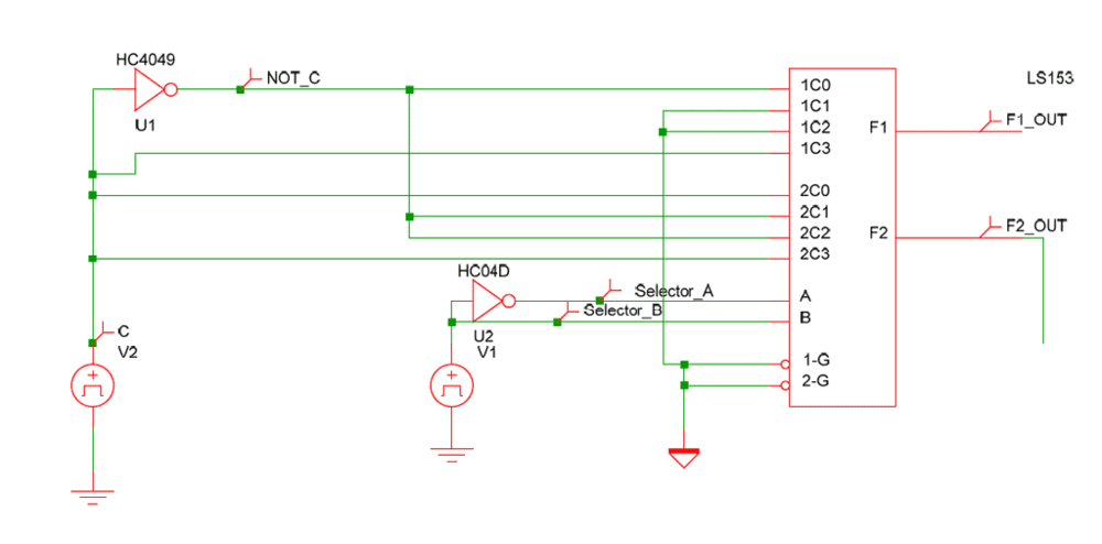
I am hoping that you could help me understand why my simple circuit is not generating any outputs.
I used LS153 to design a circuit giving two outputs (4 to 1 conversion) on SIMETRIX.
The circuit when 'run' gets the required inputs (as I see them as a square waveform graphs) but the device is not generating outputs.
Would you be able to spare a moment to offer some clues as to what might be missing?
The inputs generated are as per the below table:
Outputs F1 and F2 will be true for AB and C states as listed:
A | B | C | F1 | F2 |
0 | 0 | 0 | 1 | 0 |
0 | 0 | 1 | 0 | 1 |
0 | 1 | 0 | 0 | 1 |
0 | 1 | 1 | 0 | 0 |
1 | 0 | 0 | 0 | 1 |
1 | 0 | 1 | 0 | 0 |
1 | 1 | 0 | 0 | 0 |
1 | 1 | 1 | 1 | 1 |
Thank you all for any clues,