Master1022
- 590
- 116
- TL;DR
- This question is about comparing two methods in a stiffness matrix analysis question - using symmetry on half of the structure vs. introducing a new joint at the load
Hi,
In the question outlined in the images (apologies for the poor quality of the scans), the chosen solution has opted to use a symmetry argument and proceed from there.
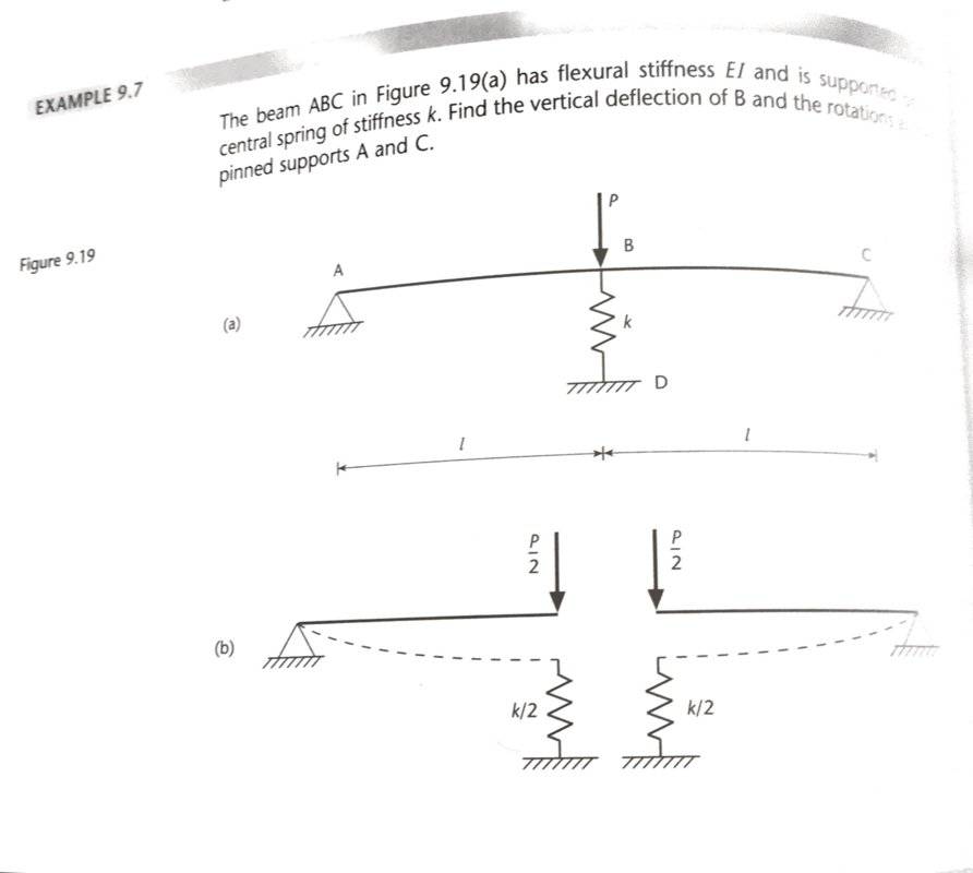
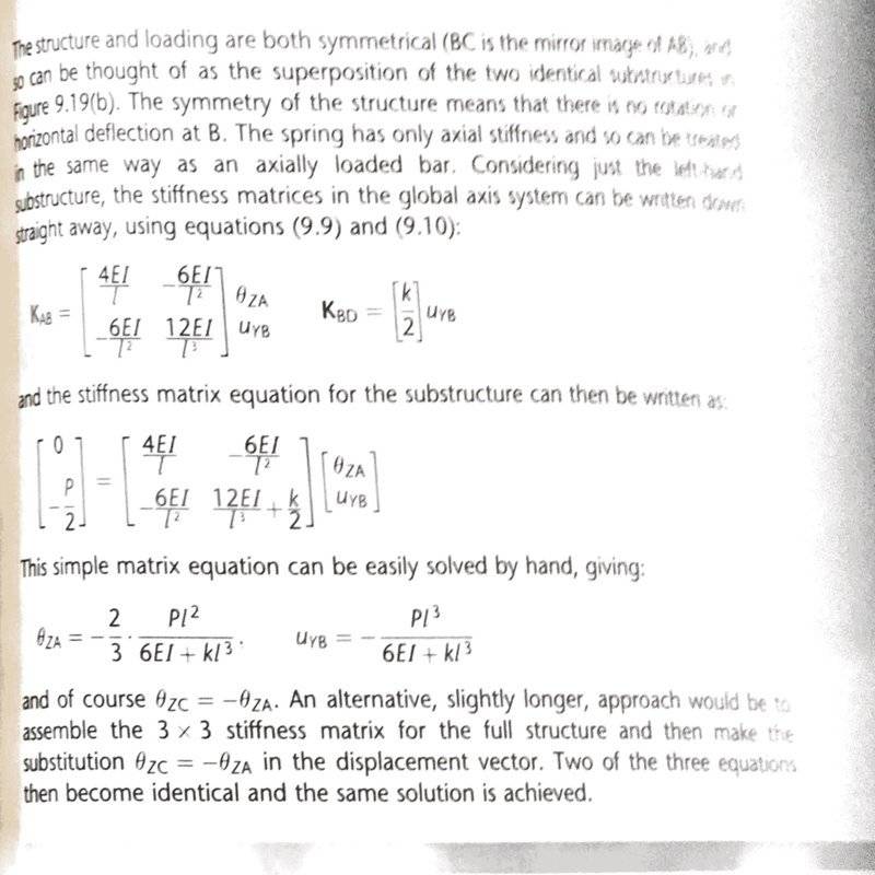
Question is from "Structures: theory and analysis" by Williams & Todd
My question is: How could we approach the same problem by introducing an extra node at the point where the load [itex]P[/itex] acts?
Method: I believe that all we would need to do if we were considering an extra joint would be to effectively double the entry in the bottom right corner of the global stiffness matrix: (i.e.
[tex]K =<br /> \begin{pmatrix}<br /> \frac{4EI}{l} & \frac{-6EI}{l^2} \\<br /> \frac{-6EI}{l^2} & (\frac{24EI}{l^3} + k)\\<br /> \end{pmatrix}[/tex]
and changing the force vector to: [tex]F = \begin{bmatrix} 0 \\ -P \\ \end{bmatrix}[/tex]
I thought of doubling the bottom right entry of K as we would be adding it to itself again in another 2 x 2 global stiffness matrix and that would be the only parameter that we care about within [itex]K_{BC}[/itex]
However, solving this yields different answers (letting EI = 1 and l = 1 for ease of typing):
[tex]\begin{bmatrix} \theta_{z_A} \\ u_{y_b} \\ \end{bmatrix} = \frac{-P}{15 + k} \begin{bmatrix} \frac{3}{2} \\ 1 \\ \end{bmatrix}[/tex].
Can anyone see where I have gone wrong in my thinking here?
Thanks in advance
In the question outlined in the images (apologies for the poor quality of the scans), the chosen solution has opted to use a symmetry argument and proceed from there.
Question is from "Structures: theory and analysis" by Williams & Todd
My question is: How could we approach the same problem by introducing an extra node at the point where the load [itex]P[/itex] acts?
Method: I believe that all we would need to do if we were considering an extra joint would be to effectively double the entry in the bottom right corner of the global stiffness matrix: (i.e.
[tex]K =<br /> \begin{pmatrix}<br /> \frac{4EI}{l} & \frac{-6EI}{l^2} \\<br /> \frac{-6EI}{l^2} & (\frac{24EI}{l^3} + k)\\<br /> \end{pmatrix}[/tex]
and changing the force vector to: [tex]F = \begin{bmatrix} 0 \\ -P \\ \end{bmatrix}[/tex]
I thought of doubling the bottom right entry of K as we would be adding it to itself again in another 2 x 2 global stiffness matrix and that would be the only parameter that we care about within [itex]K_{BC}[/itex]
However, solving this yields different answers (letting EI = 1 and l = 1 for ease of typing):
[tex]\begin{bmatrix} \theta_{z_A} \\ u_{y_b} \\ \end{bmatrix} = \frac{-P}{15 + k} \begin{bmatrix} \frac{3}{2} \\ 1 \\ \end{bmatrix}[/tex].
Can anyone see where I have gone wrong in my thinking here?
Thanks in advance