lorenz0
- 151
- 28
- Homework Statement
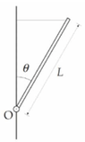
- A homogeneous rod of mass ##m## and length ##L## can rotate without friction around the pin ##O##. The rod is balanced in the situation in the figure thanks to the presence of an ideal horizontal rope fixed to the vertical wall, which causes the angle between the wall and rod to be ##\theta##. Calculate: 1) Tension ##T## of the rope and the reaction ##N## of the pin; 2) the kinetic energy of the rod when it reaches the vertical position after the rope has been cut; 3) the tangential speed of the free end of the rod when it reaches the vertical position
- Relevant Equations
- ##\tau=r\times F, F=ma, E=U_{grav}+E_K, E_{K_rot}=\frac{1}{2}I\omega^2##
1) ##LT\sin(\frac{\pi}{2}-\theta)-\frac{L}{2}mg\sin\theta=0\Rightarrow T=\frac{mg}{2}\tan\theta##.
##N_{x}-T=0, N_{y}-mg=0\Rightarrow N=\sqrt{N_x ^2+N_y ^2}=mg\sqrt{(\frac{\tan\theta}{2})^2 +1}##
2) ##E_{k_{fin}}=mg\frac{L}{2}[1+\cos\theta]##
3) ##mg\frac{L}{2}[\cos\theta+1]=\frac{1}{2}I_O \omega_f^2=\frac{1}{2}(\frac{1}{12}mL^2) \omega_f^2\Rightarrow \omega_f=\sqrt{\frac{12g[\cos\theta +1]}{L}}\Rightarrow v_f=L\omega_f=\sqrt{12gL[1+\cos\theta]}##
Now the first two results are correct, but for ##v_f## the book gives ##v_f=\sqrt{3gL[1+\cos\theta]}## and I don't see why so I would appreciate an explanation. Thanks
---
##mg\frac{L}{2}[\cos\theta+1]=\frac{1}{2}I_O \omega_f^2=\frac{1}{2}(I_{CM}+m(\frac{L}{2})^2 \omega_f^2=\frac{1}{2}((\frac{1}{12}+\frac{1}{4})mL^2 ) \omega_f^2=\frac{1}{6}mL^2\omega_f^2\Rightarrow \omega_f=\sqrt{\frac{3g[\cos\theta +1]}{L}}\Rightarrow v_f=L\omega_f=\sqrt{3gL[1+\cos\theta]}##
Attachments
Last edited: